The adder is a combinational circuit that add binary digits for arithmetic computation. A combinational circuit is a kind of digital circuit that has an input, a logic circuit and an output.
For  variables, there are
  combinations of input variables and for each input combination, there is one and only one output. Therefore, output from combinational circuit is a Boolean function expressed in terms of input variables. Remember that there is only one output for an input combination.
This article we talk about adders, so you must be familiar with following concepts: Minterm, Boolean function minimization, K-map and Truth tables.
To learn about logic gates, visit following links
Binary addition
The most basic function of a digital computer is to add binary digits to perform arithmetic operations like humans do, except that we use decimal number system. A digital computer uses binary number. Suppose, you want to add two binary digits – A and B, where A and B represents 0 or 1.
If A = 0 and B = 0, then sum = 0 + 0 = 0
If A = 0 and B = 1, then sum = 0 + 1 = 1
If A = 1 and B = 0, then sum = 1 + 0 = 1
If A = 1 and B = 1, then sum = 1 + 1 = 0 and carry = 1
When the inputs are two binary digits. It produce at most two output.
- A sum
- A carry (the last operation above results in a carry)
Adders
Binary addition is the motivation behind the adder circuit and there are many types of adder circuits. There are two type of basic adders that help to build complex circuits.
- Half adder
- Full adder
Half Adder
The half adder circuit perform 2 bit addition. The two bit addition produce output called a Sum and a Carry. The outputs are binary functions, the functions of sum and carry helps in designing a logic circuit for half adder. The process of deriving a function and circuit design in given below.
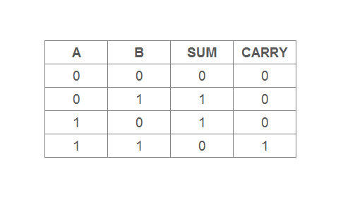
Half Adder Truth Table
The truth table of half-adder shows all combinations of its input values which is  rows. Each row represents a single combination. The 2 columns are for input variables – A and B and the other two columns are for outputs: Sum and Carry.
Logic functions
The logic functions are for the output of a combinational circuit. You will derive a logic function for half-adder circuit using truth table. The process of deriving logic function is
Step 1: Select all the rows from truth table that result in 1 in sum column or carry column.
Step 2: Create a sum of product function using the minterms you obtained in step 1.
Step 3: Minimize the Boolean function obtained to get the minimum sum of product function for the output sum and carry.
For example
Step 1:
A'B, AB' for sum;
A.B for carry.

Step 2:
Sum = A'B + AB'
Carry = A.B

Step 3:
K-MAP to minimize the Boolean function.
Draw two variable maps for sum and carry using the Boolean functions. Mark the cell as 1 if it corresponds to a minterm in the respective map.
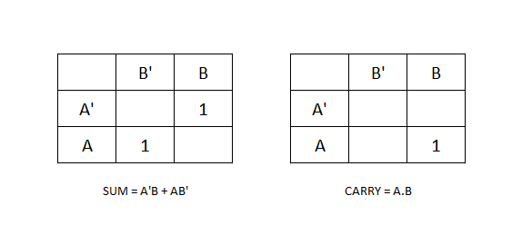
The given functions are mapped into the K-maps, but cannot be minimized because the 1s cannot be grouped, therefore, the final function is
Sum = A ⊕ B
Carry = A . B
Logic Symbol – Half Adder
Sometimes drawing complex circuit such as a 4 bit adder, needs many components and a detailed diagram for each component is not necessary. This may add to complexity. You can use a logic symbol instead to simplify things. A logic symbol for half adder is given below.
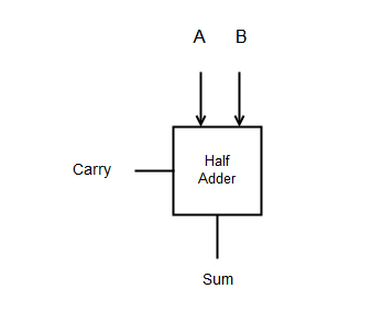
The logic diagram shows all the features of a half adder such as inputs and sum and carry. Any other details is not necessary if you are using many such adders.
Half Adder Logic Circuit
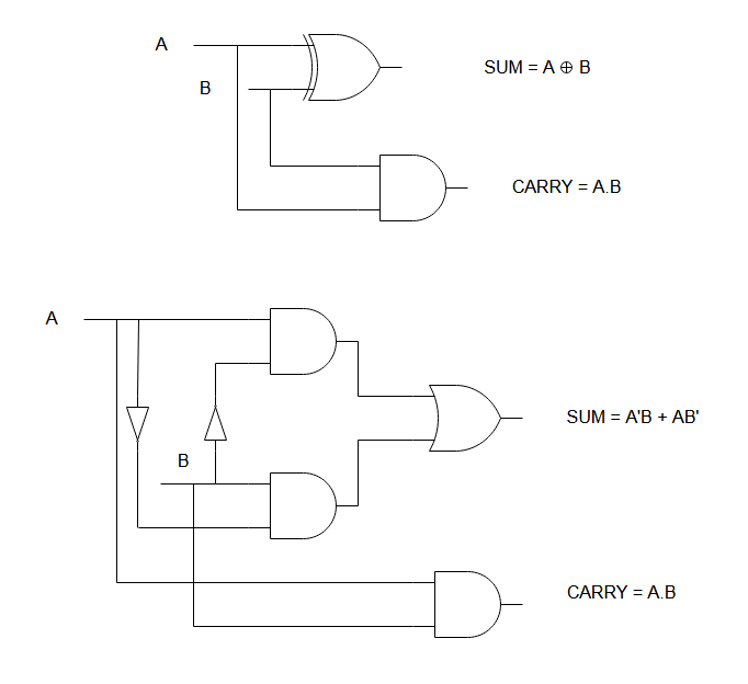
The output functions for sum and carry are the basic for designing a logic circuit for half adder circuit. Take a look at the function
Sum = A'B + AB'
Carry = A.B
You can clearly tell that the sum needs two AND gate and an OR gate to represent this circuit in real world. Similarly, Carry need a single and gate. You should note that the sum function is nothing but XOR function, so you can still minimize the number of gates by using one XOR gate and an AND gate to represent a half adder circuit.
Full Adder
Full adder is another type of adder that adds 3 binary bits. It has 3 inputs and 2 output – Sum and Carry-out.
Three-bit binary addition
A three-bit binary addition or more is required in some digital circuits. In this case, the first two bits are evaluated first and then the result is evaluated with the third variable. See the example below.
(0 + 0) + 0 = 0
(0 + 0) + 1 = 1
Full Adder Truth table
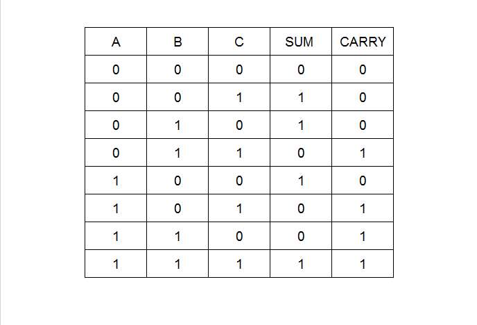
The truth table of full adder has 3 columns for input variables and 2 columns for output. The total combinations of input variables give the number of rows which is  rows.
rows.
Logic functions
Similar to half-adder, you can derive the logical functions for outputs of a full adder using the truth table. You need to follow the same process as in the case of half adder.
Step 1: list all the minterms that has 1 as result for sum.
Step 2: Make a sum of product equation using the minterms.
Sum = A'B'C + A'BC' + AB'C' + ABC
Carry = A'BC + AB'C + ABC' + ABC
Step 3: Use K-Map to minimize the equation for sum and carry. While using the K-Maps for full adder, you may observe that the carry function can be grouped and minimized and the resulting functions are
Sum = A'B'C + A'BC' + AB'C' + ABC = A ⊕ B ⊕ C
Carry = A'BC + AB'C + ABC' + ABC = AC + AB + BC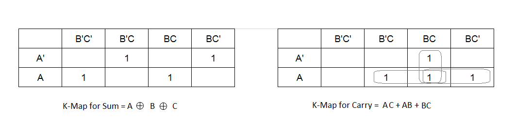
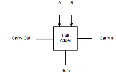
Logic Symbol – Full Adder
The logic diagram of full adder is not different from the logic diagram of the half-adder, except that one of the input of a full adder is Carry In and one output is Carry Out.
Full Adder Logic Circuit
The logic diagram is derived from the equation of outputs. The equation shows that you need two XOR gate and an OR gate. Also, you can represent the circuit using four AND gates and a single OR gate for sum and three AND gates with a single OR gate for carry.
Sum = A'B'C + A'BC' + AB'C' + ABC
Carry = BC + AC + AB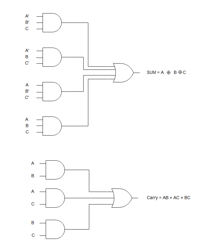
In the next article, you will learn about more complex adders such as 4 bit adder, n-bit parallel adder and so on.
References
- Mano, M. Morris. 1984. Digital Design. Pearson.
- Shjiva, Sajjan G. 1998. Introduction to Logic Design. New York: Marcel Dekker, Inc .