3-Variable K-Map
The K-map or Karnaugh map is a graphical tool to minimize a boolean function. From the previous article, you know how a boolean function represented in canonical sum of product is changed into sum of product form using K-map. Also, the k-map is nothing but the same truth table in a matrix form where each of the cell is a minterm.
In this post, you will learn about a 3-variable with an example.
Truth Table for 3-Variable Map
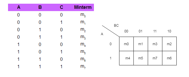
It is a well-known fact that K-map is nothing but a different representation of truth table; therefore, a truth table for 3 variables will contain  rows. This also means that the K-map would contain total of 8 cells, each for a row in the truth table.
Consider the following truth table for three variables – A, B, and C.
Let us understand the characteristics of the 3-variable K-map because it is very important to understand and use this map for boolean function minimization.
Characteristics of a 3-variable K-map
- The truth table has total of 8 rows which corresponds to 8 cells of the 3-variable K-map.
- Each cell differs in only one variable to its neighbor, both horizontally and vertically.
- To minimize the terms in a boolean function, mark a cell as 1 if its output is 1 in the truth table and leave the rest as it is.
- To minimize the variables within each term of a cell that has 1 in K-map, start making groups of 2, 4, and 8.
- Grouping of 1s includes neighboring cells, corners and sides even though they overlap each other.
- Make larger groups if possible.
- Once all 1s are covered then you can stop.
Now that you know the 3-variable map and its characteristics. It is time to see an example.
3-Variable Map Examples
In this section, you will find examples of 3-variable map. These are some examples, you may refer to some textbooks for more examples and practice yourself.
Q1 – Plot a 3-variable map for the following function.
F = A'B'C' + A'B'C + AB'C Solution:
The function use three minterms that gives output 1 as per truth table.

Q2 – Plot a three variable map and show grouping of two for marked cells for the following function.
F = A'B'C + A'BC + ABCSolution:

Q3 – Plot a three-variable map for following function and make group of four cells that are marked as 1s.
F = A'B'C' + A'BC' + AB'C' + ABC'Solution:

You should note that both sides are overlapped and made into a group of 4 four because two side when compared have a difference of 1 variable, for example, A’B’C’ and A’BC’ has only difference of B’ and B. This applies to both – horizontal and vertical directions. The sides and corners are also neighbors of each other with a difference of 1 variable change.
Q4 – Minimize the following Boolean function using K-Map.
F = A'B'C' + A'B'C + A'BC + AB'C + ABC'Solution:
We will find the solution to this problem in step by step manner.
Step 1: Plot a 3-variable map and mark the terms from the function to 1.

Step 2: Make groups of 2, 4, or 8 and only take variables that are common in the group both horizontally and vertically.
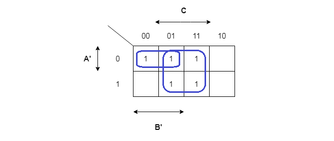
Once you have grouped all the cells with 1s into group of 2s, 4s, or 8s. List all the variables that are common vertically and horizontally. For example
//Group of two
= A'B'C' + A'B'C
= A' is common vertically
= B' is common horizontally
Our first term is A'B'.
//Group of four
= A'B'C + A'BC + AB'C + ABC
= A' + A cancel out vertically, leaving B'C + BC
= C is only common variable horizontally.
Our second term is C.
The final minimized equation is F = A'B'+ C
Rules for grouping in 3-variable map
- A single cell with 1 gives 3 literals.
- Two adjacent cell group gives 2 literals.
- Four cells with 1s will give a single literal.
In the next article, we will see how to minimize a Boolean function with 4-variable map which has 16 cells to work with.
Understanding Karnaugh Map
In the previous post, you learned about representing boolean functions as canonical sum of product and canonical product of sum; then you can minimize them in to sum of product form or product of sum form by applying boolean algebra rules.
The boolean algebra rules are difficult as the complexity of circuits grow. You cannot do a boolean minimization when there are huge truth table involving several variables. Therefore, Karnaugh maps or K-maps minimize boolean expressions with the help of graphical representations.
What is K-Map?
The Karnaugh map was invented by American physicist Maurice Karnaugh in year 1953. Hence, the name. It is a simple representation of truth table in a matrix form. For boolean minimization, we need two simple operations which are reducing the terms of the function, and eliminating variables from terms if possible.
Two Variable Map Example
Suppose we have two variables – A and B. They perform an AND operations. The truth table will show all possible input combinations as follows.
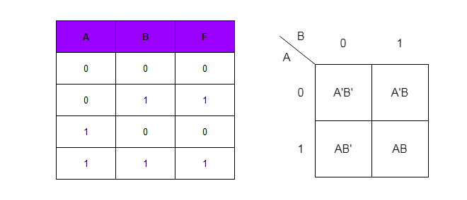
Each of the cell in the K-map represent a minterm and the two variables are represented along the vertical and horizontal direction. The difference between adjacent cell is always 1 bit – both in vertical and horizontal direction.
Vertically , A’B’ and AB’ has A variable changing from 0 to 1, that is A’ to A. Horizontally, A’B’ and A’B have variable B changing from B’ to B, that is. from 0 to 1.
Grouping Of Cells
Now look at the truth table, there are minterms that gives 1 as the output. These are shown the following figure.
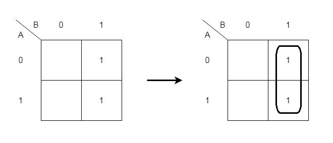
Once you have marked all the cells with output 1, you can group them into 2s, 4s or 8s. If we count only cells with 1 then the function is F = A’B + AB.
To minimize this function simply group the cells and eliminate A which is different vertically and keep B because it same vertically. In other words, vertically, A + A’ = 1. Our solution is B.
Also, If you look at the truth table, the output F column matches column B.
In the next few posts, we will explore more complex form of Karnaugh maps such as 3-variable map, 4-variable map.
Boolean Function Minimization Overview
So far you have seen, gates and truth table, and output of each gates and combinations of gated circuits. The circuit is represented in the form of a boolean function. Therefore, the process of design starts with deciding:
- number of inputs and outputs
- derive a boolean function that represents the circuit
- minimize the boolean function to obtain a function with minimum number of gates.
The digital design process is to minimize the number of gates by two methods.
- reduce the number of terms in the boolean function.
- reduce the literals or gates from the function.
What are the Methods of Minimizing a Boolean function?
There are three three ways to design boolean circuit.
- Use boolean algebra rules to minimize the circuits
- Use map methods such Karnaugh map, Quine-McClukey tabular method.
- Use software programs suchs VHDL, Verilog, or VSLI and so on.
Since, it is not possible to make a extremely complex circuits with boolean algebra rules or by map methods. Today, we use software programs to design the logic and test the results before implement them as a circuits.
Therefore, for an understanding we can use boolean algebra rules because the software are no different as they also implement there rules to create a circuit design.
Boolean Algebra Rules
Here are the rules for boolean algebra that can be used for minimizing the circuits.
| Boolean Algebra Law | Example |
| Annulment | X + 1 = X , X . 0 = 0 |
| Identity | X + 0 = X , X . 1 = X |
| Idempotent | X + X = X , X . X = X |
| Complement | X + X’ = 1 , X . X’ = 0 |
| Double Negation | (X’)’ = X |
| Commutative | X + Y = Y + X , X . Y = Y . X |
| Associative | X + ( Y + Z) = (X + Y ) + Z , X . ( Y . Z ) = (X . Y ) . Z |
| Distributive | X + ( Y . Z ) = (X + Y ) . ( X + Y ) , X . ( Y + Z ) = X.Y + X.Z |
| DeMorgan’s Theorem | (X + Y)’ = X’ . Y’ , (X . Y)’ = X’ + Y’ |
| Absorbtion | A + A.B = A |
Boolean Minimization Example
In this example, we created a circuit for the function $F = A + A’ \cdot B$ with two gates. See the image below.
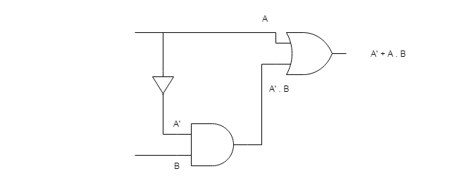
The procedure to minimize the function is given below. You need to apply the rules such that there is less terms and for each term try reducing the variables.
F = A + A'B
= A + AB + A'B   by absorption law A + AB = A
= A + B(A + A')  by distributive law
= A + B(1)       by complement law A + A' = 1
= A + B is the solution
If we design the circuit again and compare the truth table, you will understand why a boolean minimization is necessary.

Truth Table
The truth table of both the functions are given below.
| A | A’ | B | A’ . B | A + A’.B | A + B |
| 0 | 1 | 0 | 0 | 0 | 0 |
| 0 | 1 | 1 | 1 | 1 | 1 |
| 1 | 0 | 0 | 0 | 1 | 1 |
| 1 | 0 | 1 | 0 | 1 | 1 |
The truth table above display output from both the functions and we find that the output is same. In fact, the output A + B is achieves same results with fewer number of gates. Hence, reducing the cost of the circuit.
In the next article, you will learn about representing a boolean function in different forms such as SOP or POS and minimizing boolean function using map methods.
Boolean Algebra Basics
Boolean algebra basics contains a set of axioms, postulates, and theorems. It also contains a set of elements and operators. The operators are called the binary operators.
A set of elements is a collection of objects that have similar properties. This definition of a set is debatable, but that is not the scope of this article. The general notion of set is that it contains elements of similar nature.
Example of Set:
S = \{2, 4, 6, 8 \}The notation  mean “element x is in set S”.
The * is a binary operator if for any pair  it define the rule to find
  and also,
  . It is not a binary operator is
  and
and  .
.
Fundamental Postulates of Boolean Algebra
The fundamental postulates for Boolean Algebra are given below. Thought Boolean algebra was introduced by George Boole in 1845, the postulates were formulated by E.V.Huntington in 1904, that every Boolean algebra must satisfy.
We only use two variable Boolean algebra as far as digital design is concerned. The 6 postulates in Boolean algebra basics are listed below.
- Closure
- Associative law
- Commutative law
- Identity element
- Inverse
- Distributive law
Let us discuss each of them, one at a time.
Closure
A set S is closed with respect to binary operator * if for every pair of an element in set S, the binary operator specifies a rule to find an element in S.
Example,
N is set of natural numbers,
\begin{aligned}
&N = \{1, 2, 3, 4, ...\}
\end{aligned}
Suppose + is the binary operator, then you take any number a and b in N,
\begin{aligned}
&a + b \in N\\
&3 + 2 = 5\\
&2, 3 \in N \\
&5 \in N.\\
\end{aligned}
but when we do subtraction.
\begin{aligned}
&a - b \notin N\\
&2 - 4 = -2\\
&2, 4 \in N \hspace{3px} and \hspace{3px} -2 \notin N\\
\end{aligned}
The subtraction (-) is not a binary operator because it does not satisfy closure property.
Associativity Law
A binary operator (*) is associative on a set S whenever following is true.
\begin{aligned}&x*(y*z) = (x * y) * z , \\\\
&\forall x, y, z \in S
\end{aligned}
For example, the multiplication  is an associative binary operator on a set of natural numbers N.
\begin{aligned}
&= 2 \times ( 4 \times 1)\\
&= 2 \times 4 = 8\\
\end{aligned}
It is equal to the following.
\begin{aligned}
& = (2 \times 4) \times 1\\
& = 8 \times 1 = 8
\end{aligned}
But addition  is also an associative binary operator.
\begin{aligned}
&= 2 + ( 4 + 5)\\
&= 2 + 9 = 114
\end{aligned}
Is equal to the following equation.
\begin{aligned}
&= (2 + 4) + 5\\
& = 6 + 5 = 11
\end{aligned}
Communicative Law
A binary operator * is communicative on a set S, whenever
\begin{aligned}
&x * y = y * x, \\\\
&\forall x, y \in S
\end{aligned}
The addition operator (+) and multiplication (x) are communicative on a set of natural numbers (N).
For example,
\begin{aligned}
&5 + 4 = 4 + 5 = 9\\\\
&and\\\\
&4 \times 2 = 2 \times 4 = 8
\end{aligned}
Identity Element
A set S has an identity element with respect to a binary operation * on S, if there exists an element  such that
\begin{aligned}
&x * e = e * x = x,\\\\
&for \hspace{3px} any \hspace{3px} x \in S
\end{aligned}
The identity element for a set S is always unique to the set. Consider the following example, where + is the binary operation on a set of integers, Z and 0 is the identity element.
\begin{aligned}
Z = 4 + 0 = 0 + 4 = 4\\
Z = 8 + 0 = 0 + 8 = 8
\end{aligned}
Inverse
A set S with identity element  is said to have an inverse with respect to binary operation *, whenever, for all
\begin{aligned}
&x \in S,\\
&\exists y \in S \mid x * y = e\end{aligned}
Let us take the previous example of addition + on a set of integers Z, with identity element 0.
Let x be an element in Z,
\begin{aligned}
&x \in Z\\
&x = 5\\
\end{aligned}
Then, -x also belong to Z, let us call it y.
\begin{aligned}
&y \in Z\\
&y = -5\\
&x + y = 0
\end{aligned}
Therefore, a set of integers have inverse with respect to binary operation – addition.
Distributive Law
The distributive law is a very important property of algebraic structures. If * and. are two binary operations on set S, then * is said to distributive over. whenever
\begin{aligned}
&x * ( y . z) = (x * y) . (x * z)\\\\
&\forall x,y,z \in S
\end{aligned}
Also, . is distributive over * whenever
\begin{aligned}
&x \cdot (y \cdot z) = (x \cdot y) \cdot (x \cdot z)\\\\
&\forall x, y, z \in S
\end{aligned}
From the above postulate in Boolean algebra basics, it clear that all binary operators cannot hold all six properties. In fact, the modern algebra studies these algebraic structures formally and trying to find interesting properties. The topics of study are groups, sub-groups, monoid, rings, and fields.
Derived Logic Gates
There are some logic gates that are derived from the basic gates such as AND, OR and NOT by combining them into single unit. These kinds of logic gates are very important for creating complex logic circuits and called Derived logic gates.
Types of Derived Gates
. Here is a list of derived gate types. Each of these gates are derived from combining two or more basic gate types.
- NAND Gate
- NOR Gate
- XOR Gate
- XNOR Gate
NAND Gate
A NAND gate is ‘Not AND’ derived logic gate, it is combination of NOT and AND gate types. The NAND gives same output as an AND gate but invert the output, due to a NOT associated to the output.
The logic symbol for a two input NAND gate is given below.
- It has two input labeled as A and B which accept binary value – 1 or 0.
- NAND logic is applied to the input values and sent to output labelled as Y.
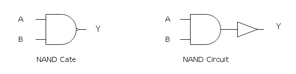
NAND gate accept different combination of A and B, the NAND operation is denoted as (A.B)’. It means that the output of an AND gate is complemented.
Truth Table for NAND
A two input NAND gate can have 2n = 22 = 4 combinations of input values. The value n is number of inputs to a gate and all combination of input values and their output is presented in a tabular form called the Truth Table.
Sometimes looking at the truth table itself you can tell, which logic gate it belongs to.
Truth table has rows and columns where rows represent a combination of input values. The column represents the number of inputs and an output from the logic gate.
The truth table for NAND gate is given low.
| A | B | Y = (A . B)’ |
| 1 | 1 | 0 |
| 1 | 0 | 1 |
| 0 | 1 | 1 |
| 0 | 0 | 1 |
When A = 1 and B= 1, the output of AND gate is inverted to produce output Y = 0. If A = 0 and B = 1, the output of AND is 0, but when inverted it becomes 1.
NOR Gate
A derived logic gate – NOR gate is “Not OR” which means it is made of two simple gates – OR and NOT. The OR logic receives the input signals, process it and sent it to output, but it is inverted by an inverted NOT gate associated to output.
Similar to a NAND gate, a symbol for two input NOR gate given below.
It has two inputs – A and B that accepts binary values. The NOR logic is applied, and the output is sent to terminal labeled as Y.
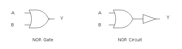
The NOR logic receives inputs – A and B and the NOR operation is shown as (A + B)’ where (A+B) is an OR operation.
Truth Table for NOR
The truth table for a two input NOR gate is similar to NAND gate except for the output.
The inputs combinations are rows and the columns are inputs and an output from the NOR gate. The truth table for a NOR gate is given below.
| A | B | Y = (A + B)’ |
| 1 | 1 | 0 |
| 1 | 0 | 0 |
| 0 | 1 | 0 |
| 0 | 0 | 1 |
Let the input combination be A = 1 and B= 0, then the logic of OR says ‘if any input of OR is 1, then the output is 1.” But output Y = 1 is inverted in NOR and becomes 0.
XOR Gate
XOR or Exclusive-OR is another derived logic gate which is made of simple logic gates such as NOT, OR and AND. The output Y is high (1) for XOR when any input A or B is high (1), otherwise it is low (0). The XOR has a wide verity of application in digital circuits.
The logic gate symbol for a two input XOR gate is given below. The XOR gate construct is little bit complex then the rest of the derived gates.
It has two input which accepts a 1 or 0 as input values. The input gates are labeled as A and B whose output is sent to Y.
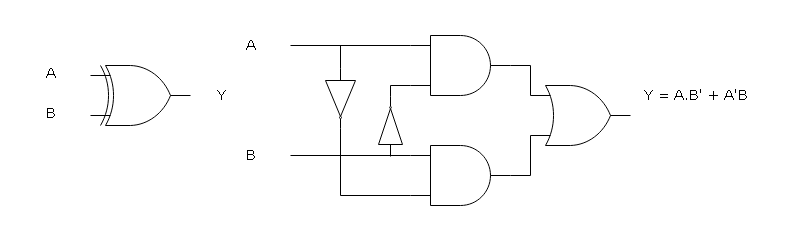
Like other gates, XOR is also 4 rows of input combinations for 2 inputs. The columns are inputs and a single output Y. The logic operation of XOR is denoted as a Boolean function – (A’B) + (A.B’). The truth table for Exclusive-OR is given below.
| A | B | Y = (A.B’) + (A’.B) |
| 1 | 1 | 0 |
| 1 | 0 | 1 |
| 0 | 1 | 1 |
| 0 | 0 | 0 |
Suppose, A = 1 and B = 1, then the output Y = 0, this is because both inputs cannot be same even though they are high. But if A = 0 and B = 1, then output Y = 1.
XNOR Gate
The derived logic gate – XNOR is opposite of XOR gate, if both inputs of a XNOR gate are similar then the output is high (1), otherwise low (0).
The logic gate symbol for a two input XNOR is given below. The inputs are labeled as A and B which accept a binary input – 1 or 0.
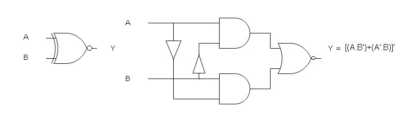
The output is labeled as Y = [(A . B) + (A’. B’)]’ to denote that the XNOR is also a Boolean function like XOR. The logic symbol of XNOR gate is a circle with a dot in center.
Truth Table
Like other gates, XNOR is also 4 rows of input combinations for 2 inputs. The columns are inputs and a single output Y. The truth table for Exclusive- NOR is given below.
| A | B | Y = [(A.B’)+(A’.B)]’ |
| 1 | 1 | 1 |
| 1 | 0 | 0 |
| 0 | 1 | 0 |
| 0 | 0 | 1 |
Suppose, A = 1 and B = 1, then the output Y = 1, this is because both inputs must be same for output to be high. But if A = 0 and B = 1, then output Y = 0.
References
- John.F.Wakerly. 2008. Digital Design: Principles And Practices, 4/E. Pearson Education, India.
- Mano, M. Morris. 1984. Digital Design. Pearson.
- NATARAJAN, ANANDA. 2015. Digital Design. PHI Learning Pvt. Ltd.
Logic Gates
In this lesson, you will learn about -logic gates. The logic gates are building blocks of digital circuit to which voltage and current are applied to as binary logic 0 or 1. Voltage or current applied to analog circuits such as telephone systems as analog signals with continuous range from 0 to 5 V.
Binary Logic System
A digital circuit recognize only 1 and 0, so in this voltage operated circuit – a low voltage 0V is binary 0 and a high voltage 5V is binary 1.
In real world, these voltages are not absolute, but voltage has an acceptable range of values.
For example
\begin{aligned}
&3V \hspace{3px}to \hspace{3px}5V \hspace{3px}is \hspace{3px}1\\\\
&0V \hspace{3px}to \hspace{3px}0.2V \hspace{3px}is \hspace{3px}0
\end{aligned}
Positive Logic System
In this system, the low voltage to the circuit, 0V is considered as logic 1 and high voltage 5V is a 0 logic.
Negative Logic System
In this system, when the input voltage is 0V it is logic 0 and the high voltage to the input is considered as logic 1.
Basic Gates
The logic gates are the fundamental hardware devices to which input voltage is applied and it produces a specific logical response as output.
You can derive other gates from the basic logic gate types or create simple digital circuits. Understanding logic gates properly is very important in learning higher concepts in digital circuit design.
Types of Basic Gates and their Symbols
There are three types of logic gates which are listed below.
- AND Gate
- OR Gate
- Not Gate
We will discuss the derived gate types in the next section.
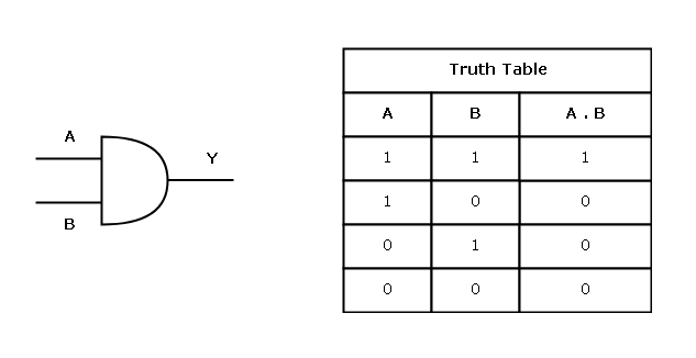
AND Gate
The AND gate work on the principle, “all or nothing”. An AND gate with two input A and B will send an output of 1, only when both A and B are 1, otherwise, the output will be false.
Output from an AND gate with all possible combination of inputs for A and B is usually written in a table called the Truth Table.
The expression  denotes an AND operation on A and B. The logic symbol and truth table for AND gate is given below.
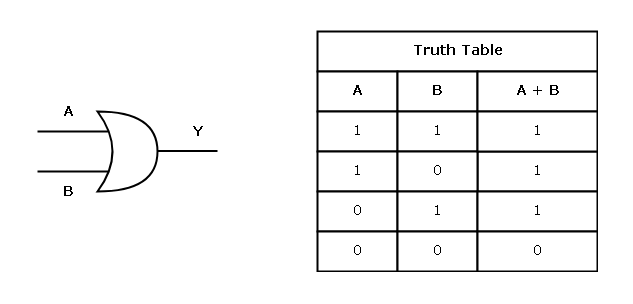
OR Gate
The logic of OR gate is different, and it says, “If any input of an OR gate is 1, then the output will be 1”. This gate does not need both input to 1 for an output to be 1.
The OR operation is denoted by a “plus” sign –  , which means A or B. The logic symbol and truth table for OR gate is given below.
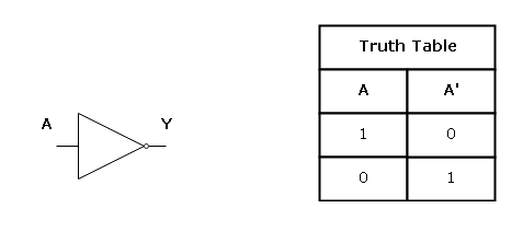
NOT Gate
The NOT gate is used as an inverter in a digital circuit. If the input is 1, then the output becomes 0 and if the input is 0, then the output is 1.
The NOT operation is denoted as A’ if performed on a single input variable A. The logic symbol and truth table for the NOT gate is given below.
These are the basic gates and building blocks of all kinds of digital circuits. In the next lesson, we will discuss about derived gates like NOR, NAND, XOR, etc.
References
- John.F.Wakerly. 2008. Digital Design: Principles And Practices, 4/E. Pearson Education, India.
- Mano, M. Morris. 1984. Digital Design. Pearson.
Binary-Coded Decimal
In the previous lesson, we learned about binary codes and how they are used for representing a distinct discrete element of information using 1s and 0s.
People use the decimal system for everything and it’s easier for them to use decimal numbers on a computer than binary numbers. But binary is what the computer understands.
So we need a system to convert decimal to binary and perform the calculation using binary numbers and convert the output back to decimal for users. This binary representation of a decimal number is called the binary coded decimal code or BCD code.
Binary-Coded Decimal (BCD code)
The binary coded decimal is a 4-bit code and each 4-bit code represents one decimal digit from 0 to 9. See the table below
| Decimal Digit | Binary Coded Decimal |
| 0 | 0000 |
| 1 | 0001 |
| 2 | 0010 |
| 3 | 0011 |
| 4 | 0100 |
| 5 | 0101 |
| 6 | 0110 |
| 7 | 0111 |
| 8 | 1000 |
| 9 | 1001 |
But there are 16 codes because  combinations. The codes from
  to
to  does not matter and are not used in BCD.
For example
The binary and BCD value of 128 is given below for your understanding.
| Binary number for 12810 | BCD Code for 12810 |
| 1000 0000 | 0001 0010 1000 |
Important points to remember
- Decimal number is
 so on, and BCD code is
  … It means they are same.
 - The binary number is not BCD, there is a difference.
- BCD coded decimal numbers need more bits. See the example above.
 so on, and BCD code is
  … It means they are same.
BCD Addition
When two BCD numbers are added then two things happen
- Sum is less than
 = decimal
- The sum is equal to or more than decimal

Suppose you add following BCD numbers
 \begin{aligned}
&4 + 3\\
&0100\\
&0011\\
&-------\\
&0111 = 7_{10}
\end{aligned}
The result is a BCD sum and less than .
First Case – when BCD sum does not have a carry
Consider another example
\begin{aligned}
&4 + 3\\
&0100\\
&0011\\
&-------\\
&0111 = 7_{10}
\end{aligned}
\begin{aligned}
&8 + 4\\
&1000\\
&0100\\
&-------\\
&1100 = 12_{10}
\end{aligned}The BCD does not allow 1100 and we need 12 as an answer in BCD. The first digit is 1 and the second digit is 2.There are 16 codes in BCD and we are using only 10 of them.
1010 + 0110 = 1 \hspace{3px} carry + 0000 = 0001 0000 = 10 \hspace{3px} in \hspace{3px}BCD \\

1011 + 0110 = 1 \hspace{3px}carry + 0001 = 0001 0001 = 11 \hspace{3px} in \hspace{3px} BCD\\

1100 + 0110 = 1\hspace{3px} carry + 0010 = 0001 0010 = 12 \hspace{3px} in \hspace{3px}BCD\\

1101 + 0110 = 1 \hspace{3px}carry + 0011 = 0001 0011 = 13 \hspace{3px} in \hspace{3px}BCD\\

1110 + 0110 = 1 \hspace{3px}carry + 0100 = 0001 0100 = 14 \hspace{3px} in \hspace{3px}BCD\\

1111 + 0110 = 1 \hspace{3px}carry + 1000 = 0001 0101 = 15 \hspace{3px} in \hspace{3px}BCD
Then whenever, you get an invalid BCD sum, add a 0110 = 6 to the result and you will get the correct BCD sum.
Second Case – when BCD sum has a carry
We now look at another case of BCD sum when the result appears to be correct, but it has a carry.
\begin{aligned}
&\hspace{13px}8+9\\
&\hspace{13px}1 0 0 0\\
&+1 0 0 1\\
&-----------\\
&\hspace{8px}1 0 0 0 1
\end{aligned}
In this case, we still add  to the 4 least significant bits.
   \begin{aligned}
&1 0 0 0 1\\
&\hspace{5px}0 1 1 0\\
& ------\\
&1 0 1 1 1\\
& = 1 \hspace{4px} carry + 0111\\
& = 0001 0111 = 17
\end{aligned}
Example – BCD Addition
In this example, we will add two decimal numbers,
\begin{aligned}
&\hspace{12px}14 \hspace{10px}+ \hspace{10px}389 = 603\\
&\hspace{12px}0 0 1 0 0 0 0 1 0 1 0 0 = 214\\
&+0 0 1 1 1 0 0 0 1 0 0 1 = 389\\
&-----------\\
&\hspace{10px}0 1 1 0 1 0 1 0 1 1 0 1\\
&\hspace{2.9em}0 1 1 0 0 1 1 0\\
&------------\\
&\hspace{10px}0 1 1 0 0 0 0 0 00 1 1 = 603
\end{aligned}
References
- John.F.Wakerly. 2008. Digital Design: Principles And Practices, 4/E. Pearson Education, India.
- Mano, M. Morris. 1984. Digital Design. Pearson.
Binary Codes
Binary codes are used to represent the distinct discrete element of information. They are patterns of 1s and 0s for a computer to understand information other than binary numbers.
The discrete elements of information are not only binary numbers but also, other types of information such as decimal numbers, etc.
What is a Binary Code?
Suppose we have an n-bit code then there are 2n combination of binary codes consists of 1s and 0s.
For example,
3-bit code has 23 = 8 codes
| Bit Combination | Codes |
|---|---|
| 0 | 000 |
| 1 | 001 |
| 2 | 010 |
| 3 | 011 |
| 4 | 100 |
| 5 | 101 |
| 6 | 110 |
| 7 | 111 |
There are 8 combinations, but the bit combination has value is between 0 to 2n – 1. A 3-bit code has bit combination from 0 to 23 – 1 = 7.
Minimum bits required
For 16 code combinations, you need minimum of 4 bits, n = 4 bits, so that 24 = 16.
For 8 codes, you need a minimum of 3 bits like in the example above,
n = 3 bits so that 23 = 8.
Maximum bit for Binary Code
There is no restriction on a number of bits that you can use for a binary code.
For example
10 decimal numbers – 0,1,2,3,4,5,6,7,8,9 can be represented using 4-bits and can also be represented using 10-bits. Let’s check this for first 5 decimal numbers.
| Decimal value | 4-bit code | 10-bit code |
|---|---|---|
| 0 | 0000 | 0000000000 |
| 1 | 0001 | 0000000010 |
| 2 | 0010 | 0000000100 |
| 3 | 0011 | 0000001000 |
| 4 | 0100 | 0000010000 |
A 4-bit code is binary representation of decimal and 10-bit code uses placeholder for each decimal number. Here the code – 0000010000 does not mean 25 = 16, but it means 5th position from right is a 1, therefore, decimal number = 4.
References
- John.F.Wakerly. 2008. Digital Design: Principles And Practices, 4/E. Pearson Education, India.
- Mano, M. Morris. 1984. Digital Design. Pearson.
- NATARAJAN, ANANDA. 2015. Digital Design. PHI Learning Pvt. Ltd.
Complements
In the previous lesson, we learned about number systems – binary, decimal, octal and hexadecimal number systems in detail. Complements are very helpful in performing subtraction and save computing time and lead to simple circuits.
Before we move to subtraction, let’s understand what complement is all about. In simple words, if there is group with have R items, and you took S items from the group, then you need the complement R-S items to complete the group.
These R-S items are called the complements.
In a number system, there is a fixed range of numbers and when you pick any number from the system, you have a complement for that number in the number system.
Types of Complements
There are two types of complements.
- Diminished Radix Complement or r-1’s complement.
- Radix Complement or r’s complement.
Diminished Radix Complement [r-1’s complement]
Suppose a number N is given
N = Number
r = base of the number
n = Number of digits in the number.
The r-1’s complement of the number is given by the formula.
(r^n - 1) - N
Radix Complement [r’s complement]
To find radix complement of a number N, where
N = Number
r. = base of the number
n = Number of digits in the number.
The r’s complement of the number is given as
r^n - N
or
r-1’s \hspace{3px}complement + 1 => [( r^n -1) – N] + 1Examples – Diminished Radix Complements
Here are some example problems for diminished radix complements.
Problem1:
Find 9’s complement of 258.
Solution:
\begin{aligned}
&N = 258\\
&r = 10\\
&n=3\\\\
&We \hspace{3px} use \hspace{3px}the \hspace{3px}formula\hspace{3px} for \hspace{3px}r-1’s \hspace{3px}complement.\\\\
&(r^n – 1) – N\\
&(10^3 – 1) – 258\\
&999 – 258\\
&The \hspace{3px} 9’s \hspace{3px}complement \hspace{3px}of \hspace{3px}258 \hspace{3px}is \hspace{3px}741.
\end{aligned}
Problem2:
Find 1’s complement for 1101.
Solution:
In the given problem,
\begin{aligned}
&N = 1101\\
&r = 2\\
&n = 4\\\\
&The \hspace{3px}formula \hspace{3px}for \hspace{3px}r-1’s \hspace{3px}complement \hspace{3px}where r = 2\hspace{3px} is \hspace{3px}(r^n - 1) – N.\\\\
&(2^4 - 1) - 1101\\\\
&Note:\hspace{3px} Binary \hspace{3px}equivalent for \hspace{3px}2^4  = 10000.\\\\
&(10000 - 1)1101\\
&1111 - 1101\\
&The \hspace{3px} 1’s \hspace{3px}complement \hspace{3px}for \hspace{3px}1101 \hspace{3px}is \hspace{3px}0010.
\end{aligned}
Method 2
The second method to find the r-1’s complement is to subtract each digit in the number by r-1.
In our case, r = 2 so r – 1 = 1
Given that the 1’s complement of binary number is
\begin{aligned}
&1 – 1 = 0\\
&1 – 1 = 0\\
&1 – 0 = 1\\
&1 – 1 = 0\\\\
&Answer: 0010
\end{aligned}
Problem3:
Find 7’s complement of octal number 234.
Solution:
The range of digits for octal number is 0-to-7. Subtract each digit with 7 will give r-1’s complement for octal.
\begin{aligned}
&7 - 2 = 5\\
&7 - 3 = 4\\
&7 - 4 = 3\\\\
&The \hspace{3px} r-1's \hspace{3px} complement \hspace{3px}is \hspace{3px} 543.
\end{aligned}
Examples – Radix Complements
There are two methods to find the r’s complement of a number.
\begin{aligned}
&Method \hspace{3px}1: r^n – N\\
&Method \hspace{3px}2: r-1’s \hspace{3px}complement + 1
\end{aligned}
Problem4:
Find 10’s complement for 432.
Solution:
Given that
\begin{aligned}
&N = 432\\
&r = 10\\
&n = 3\\
&
\end{aligned}
Method 1:
\begin{aligned}
&First \hspace{3px}we \hspace{3px}will \hspace{3px}find \hspace{3px}the \hspace{3px} 10’s \hspace{3px}complement \hspace{3px}using \hspace{3px}r^n – N.\\
&r^n – N = 1000 – 432 = 568\\
&Therefore,\\
&10’s \hspace{3px}complement \hspace{3px}of\hspace{3px} 432 \hspace{3px}is \hspace{3px}568.
\end{aligned}
Method 2:
By using method 2, you need to find the 9’s complement and then add 1 to the result to get 10’s complement.
Step1: Subtract each digit by 9 to get 9’s complement.
\begin{aligned}
&9 - 4 = 5\\
&9 - 3 = 6\\
&9 - 2 = 7\\

\end{aligned}Step2: Add 1 to the result.
\begin{aligned}
&567 + 1\\
&=568\\
&568 \hspace{3px}is \hspace{3px}the \hspace{3px}10’s \hspace{3px}complement \hspace{3px}of \hspace{3px}432.
\end{aligned}
Problem5:
Find 2’s complement of the binary number 1001.
Solution:
Method 1:
We can obtain the solution in using two methods.
\begin{aligned}
&To \hspace{3px} find \hspace{3px} 2’s \hspace{3px}complement \hspace{3px}using \hspace{3px}method 1 \hspace{3px}use \hspace{3px}the \hspace{3px}formula r^n – N.\\
&Given \hspace{3px} that\\
&N = 1001\\
&r = 2\\
&n = 4\\
&r^n - N = 10000 – 1001\\\\
&\hspace{8px}\sout10000\\
&-1001\\
&\hspace{8px}----\\
&\hspace{11px}0111\\\\
&The \hspace{3px}2’s \hspace{3px}complement \hspace{3px}for \hspace{3px}1001 \hspace{3px}is \hspace{3px}0111.
\end{aligned}
Method 2:
To use second method, find the 1’s complement for 1001 and then add 1 to the result.
Step1: find the 1’s complement of 1001.
\begin{aligned}
1001 -> 0110 (1’s complement)
\end{aligned}
Step2: Add 1 to result.
\begin{aligned}
&0110 + 1 => 0111\\
&Therefore,\\
&0111 \hspace{3px}is \hspace{3px} the \hspace{3px}2’s \hspace{3px}complement \hspace{3px}of \hspace{3px}0110.
\end{aligned}
References
- John.F.Wakerly. 2008. Digital Design: Principles And Practices, 4/E. Pearson Education, India.
- Mano, M. Morris. 1984. Digital Design. Pearson.
Number Systems
Numbers are everywhere and used in many places – financial institution, statistics, engineering and so on. Without number system our daily life would be difficult.
Humans use a number system called the decimal number system and everyone can easily understand this system. You go to a store to buy something, you need a number system to count your money. Even a small thing such as making a list of its need numbers.
What is a number system?
A number belonging to a number system with:
- A base

- Coefficient
 that is between
  to
to  .
.
 that is between
  .
.Examples
Decimal with r=10 and coefficient a = 0 to 9
Binary with r=2 and coefficient a = 0 and 1
Octal with r= 8 and coefficient a = 0 to 7
Hexadecimal with r=16 and coefficient a = 0 to 9, A, B, C, D, E, F
Converting from Any Number System to Decimal System
If the base  and coefficients are given, then any number can be converted to decimal system using following
\begin{aligned}
a_{n}\cdot r^{n}+\cdots+ a_{1}\cdot r + a_{0}+a_{-1}\cdot r^{-1}+a_{-2}\cdot r^{-2}+ a_{-n-1}\cdot r^{-n-1}+ \cdots + r^{n}
\end{aligned}
Example
To convert binary number into decimal number, do following
\begin{aligned}
&1011 = 1 * 2^3 + 0 * 2^2 + 1 * 2^1 + 2^0\\\\
&= 8 + 0 + 2 + 1\\ \\
&= 11
\end{aligned}
11 is decimal equivalent of .
Example
Convert  into decimal equivalent.
Solution:
\begin{aligned}
&Integer \hspace{5px} part \rightarrow 1101\\\\
&1 * 2^3 + 1 * 2^2 + 0 * 2^1 + 1 * 2^0\\\\
&8 + 4 + 0 + 1\\\\
&13\\\\
&Decimal \hspace{5px} part \rightarrow  .011\\\\
&0 * 2^-1 + 1 * 2^-2 + 1 * 2^-3\\\\
&0 + \frac{1}{4} + \frac{1}{8}\\\\
&\frac{3}{8}\\\\
&Answer = 13 + \frac{3}{8} = \frac{(13 * 8 + 3)}{8}\\ \\
&= \frac{107}{8}\\ \\
&= 13.37
\end{aligned}
Conversions from Decimal to Other Number Systems
The decimal number system has a base  and coefficients ranging from
  .
.
Decimal to Binary
To convert from decimal from binary, divide the decimal number repeatedly until no longer possible to divide. Each time you get a quotient and remainder, divide the quotient and note the remainder. The remainders of this division put together in reverse order is the answer. See the example below.
For the fractional part, you need to multiply the decimal fraction with base repeatedly until you reach  or close to zero for the fractional part. When you multiply a fraction with base , you get two thing – an integer and a fraction.
If the fraction has not reached zero or real close to zero, multiply it with base in next iteration and check the integer and fraction part. The integer part put together is the binary equivalent for the decimal fraction. See the example below
Problem:
Convert  to binary equivalent number.
Solution:
\begin{aligned}
&\frac{25}{2} \hspace{1cm}quotient = 12, remainder = 1\\\\
&\frac{12}{2}\hspace{1cm} quotient = 6, remainder = 0\\\\
&\frac{6}{2} \hspace{1cm}quotient = 3, remainder = 0\\\\
&\frac{3}{2}\hspace{1cm} quotient = 1, remainder = 1\\\\
&\frac{1}{2}\hspace{1cm} quotient = 0, remainder = 1\\\\
\end{aligned}
Now we find the fractional part binary equivalent.
\begin{aligned}
&0.13 \cdot 2 = 0.26 => 0 + .26\\\\
&0.26 \cdot 2 = 0.52 => 0 + .52\\\\
&0.52 \cdot 2 = 1.04 => 1 + .04\\\\
&Answer: - 11001 + .001 = 11001.001
\end{aligned}
Note that the integer part is remainders written in reverse order, that is, bottom to top in the first part of the solution.
Decimal to Octal
The decimal to octal conversion is done in the same way as decimal to binary except the base  . For example
Problem:
Convert  to its octal equivalent.
Solution:
\begin{aligned}
&\frac{235}{8}\hspace{1cm} quotient = 29, remainder = 3\\\\
&\frac{29}{8} \hspace{1cm}quotient = 3, remainder = 5\\\\
&\frac{3}{8} \hspace{1cm}quotient = 0, remainder = 3\\\\
&Answer: - 353
\end{aligned}
Decimal to Hexadecimal
The hexadecimal number has a base  and we need to divide decimal number with base to get the hexadecimal equivalent, but hexadecimal digits
  are
are  .
.
\begin{aligned}
&\frac{2344}{16} \hspace{1cm}quotient = 146, remainder = 8\\\\
&\frac{146}{16} \hspace{1cm}quotient = 9, remainder = 2\\\\
&\frac{9}{16} \hspace{1cm}quotient = 0, remainder = 9\\\\
&Answer: The \hspace{5px} hexadecimal \hspace{5px}equivalent \hspace{5px}of \hspace{5px}2344\hspace{5px} is \hspace{5px}928.
\end{aligned}
Conversions to Binary
Now we convert other number system to Binary system such as Octal to Binary, Hexadecimal to Binary numbers.
Octal to Binary
To convert octal to binary, convert each digit of the octal number to its binary equivalent, but you are only allowed to use 3-bit positions because of  which is the maximum range of octal coefficient. For example
Problem:
Convert  into its binary equivalent.
Solution:
\begin{aligned}
&2 \rightarrow 0 1 0\\\\
&5 \rightarrow 1 0 1\\\\
&6 \rightarrow 1 1 0\\\\
&Answer: The \hspace{5px}binary \hspace{5px}equivalent \hspace{5px}is \hspace{5px}010 \hspace{5px}101 \hspace{5px}110
\end{aligned}
Hexadecimal to Binary
We use 4 bits to convert each digit in a hexadecimal number to get the binary equivalent. This is because  in decimal, the maximal value allowed in hexadecimal number. For example
Problem:
Convert  into binary equivalent.
Solution:
\begin{aligned}
&2\hspace{1cm} C \hspace{1cm} D\hspace{1cm}3\\
&0010\hspace{12px}1100\hspace{17px}1101\hspace{17px}0011\\\\
&The\hspace{5px} binary\hspace{5px}  equivalent \hspace{5px} of \hspace{5px} 2CD3 \hspace{5px} is \hspace{5px} 0010 \hspace{5px} 1100\hspace{5px}  1101 \hspace{5px} 0011
\end{aligned}
Binary to Other Number Systems
Binary to Octal
To convert from binary to octal use 3-bit position and convert it into its decimal equivalent.
- For integer part 3 bit from left to right
- For fractional part 3 bit from right to left
This will give you the octal equivalent of binary number. For example,
\begin{aligned}
&1001.0101 \rightarrow 001 \hspace{5px}110\hspace{5px} . 010 \hspace{5px}100\\
 &\hspace{2cm}1  \hspace{15px} 6 \hspace{15px} . 2  \hspace{15px}  1\\\\
&Answer: - The\hspace{5px} octal\hspace{5px} equivalent \hspace{5px}is \hspace{5px}16.21.
\end{aligned}
Binary to Hexadecimal
Group the given binary number into a group of four and then convert the each of the group into the decimal equivalent to get the hexadecimal digit and group all the digits found to get the hexadecimal number. For example
Problem:
Convert the given binary number 110101011100 into hexadecimal equivalent.
Solution:
Given binary number can be separated into group of four.
\begin{aligned}
&110101011100 \rightarrow 1101 \hspace{5px}0101 \hspace{5px} 1100\\
& \hspace{2.65cm}13\hspace{15px}    5   \hspace{19px}12\\
&\hspace{2.65cm}D \hspace{16px} 5 \hspace{20px}  C
\end{aligned}
Therefore, the hexadecimal equivalent number is D5C.
Other Number Systems
Octal to Hexadecimal
We use a very simple procedure to convert octal to hexadecimal number. You can do this two easy steps.
- Convert Octal to Binary number.
- Convert the Binary number obtained into hexadecimal.
In the previous section, we learned about converting octal to binary and binary into hexadecimal. In this section, you have to use that knowledge in converting octal to hexadecimal. For example,
Problem:
Convert the given octal number  into Hexadecimal equivalent.
Solution:
Step 1: Convert the octal into binary number.
\begin{aligned}
&2 \hspace{1cm} 3   \hspace{1cm}4\\
&010\hspace{17px} 011 \hspace{17px} 100
\end{aligned}
Step 2: Convert the binary number into a hexadecimal number.
\begin{aligned}
&Binary \hspace{5px}Number \rightarrow 010011100\\
\end{aligned}
Step 3: Group the binary number into groups of four bits from left to right.
\begin{aligned}
& 0000 \hspace{5px}1001 \hspace{5px}1100\\
&0 \hspace{2em}9    \hspace{2em}12
\end{aligned}
Step 4: Convert the result into a hexadecimal number. Therefore, the hexadecimal equivalent is  .
.
Hexadecimal to Octal
If you reverse the process given in octal to hexadecimal conversion, you will get an octal equivalent for hexadecimal number.