There are some logic gates that are derived from the basic gates such as AND, OR and NOT by combining them into single unit. These kinds of logic gates are very important for creating complex logic circuits and called Derived logic gates.
Types of Derived Gates
. Here is a list of derived gate types. Each of these gates are derived from combining two or more basic gate types.
- NAND Gate
- NOR Gate
- XOR Gate
- XNOR Gate
NAND Gate
A NAND gate is ‘Not AND’ derived logic gate, it is combination of NOT and AND gate types. The NAND gives same output as an AND gate but invert the output, due to a NOT associated to the output.
The logic symbol for a two input NAND gate is given below.
- It has two input labeled as A and B which accept binary value – 1 or 0.
- NAND logic is applied to the input values and sent to output labelled as Y.

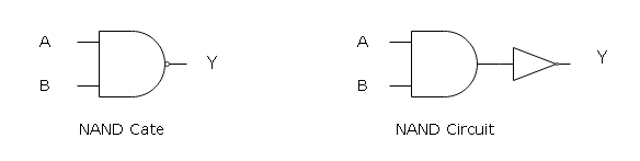
NAND gate accept different combination of A and B, the NAND operation is denoted as (A.B)’. It means that the output of an AND gate is complemented.
Truth Table for NAND
A two input NAND gate can have 2n = 22 = 4 combinations of input values. The value n is number of inputs to a gate and all combination of input values and their output is presented in a tabular form called the Truth Table.
Sometimes looking at the truth table itself you can tell, which logic gate it belongs to.
Truth table has rows and columns where rows represent a combination of input values. The column represents the number of inputs and an output from the logic gate.
The truth table for NAND gate is given low.
| A | B | Y = (A . B)’ |
| 1 | 1 | 0 |
| 1 | 0 | 1 |
| 0 | 1 | 1 |
| 0 | 0 | 1 |
When A = 1 and B= 1, the output of AND gate is inverted to produce output Y = 0. If A = 0 and B = 1, the output of AND is 0, but when inverted it becomes 1.
NOR Gate
A derived logic gate – NOR gate is “Not OR” which means it is made of two simple gates – OR and NOT. The OR logic receives the input signals, process it and sent it to output, but it is inverted by an inverted NOT gate associated to output.
Similar to a NAND gate, a symbol for two input NOR gate given below.
It has two inputs – A and B that accepts binary values. The NOR logic is applied, and the output is sent to terminal labeled as Y.

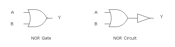
The NOR logic receives inputs – A and B and the NOR operation is shown as (A + B)’ where (A+B) is an OR operation.
Truth Table for NOR
The truth table for a two input NOR gate is similar to NAND gate except for the output.
The inputs combinations are rows and the columns are inputs and an output from the NOR gate. The truth table for a NOR gate is given below.
| A | B | Y = (A + B)’ |
| 1 | 1 | 0 |
| 1 | 0 | 0 |
| 0 | 1 | 0 |
| 0 | 0 | 1 |
Let the input combination be A = 1 and B= 0, then the logic of OR says ‘if any input of OR is 1, then the output is 1.” But output Y = 1 is inverted in NOR and becomes 0.
XOR Gate
XOR or Exclusive-OR is another derived logic gate which is made of simple logic gates such as NOT, OR and AND. The output Y is high (1) for XOR when any input A or B is high (1), otherwise it is low (0). The XOR has a wide verity of application in digital circuits.
The logic gate symbol for a two input XOR gate is given below. The XOR gate construct is little bit complex then the rest of the derived gates.
It has two input which accepts a 1 or 0 as input values. The input gates are labeled as A and B whose output is sent to Y.

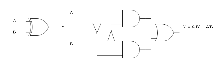
Like other gates, XOR is also 4 rows of input combinations for 2 inputs. The columns are inputs and a single output Y. The logic operation of XOR is denoted as a Boolean function – (A’B) + (A.B’). The truth table for Exclusive-OR is given below.
| A | B | Y = (A.B’) + (A’.B) |
| 1 | 1 | 0 |
| 1 | 0 | 1 |
| 0 | 1 | 1 |
| 0 | 0 | 0 |
Suppose, A = 1 and B = 1, then the output Y = 0, this is because both inputs cannot be same even though they are high. But if A = 0 and B = 1, then output Y = 1.
XNOR Gate
The derived logic gate – XNOR is opposite of XOR gate, if both inputs of a XNOR gate are similar then the output is high (1), otherwise low (0).
The logic gate symbol for a two input XNOR is given below. The inputs are labeled as A and B which accept a binary input – 1 or 0.
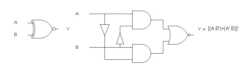
The output is labeled as Y = [(A . B) + (A’. B’)]’ to denote that the XNOR is also a Boolean function like XOR. The logic symbol of XNOR gate is a circle with a dot in center.
Truth Table
Like other gates, XNOR is also 4 rows of input combinations for 2 inputs. The columns are inputs and a single output Y. The truth table for Exclusive- NOR is given below.
| A | B | Y = [(A.B’)+(A’.B)]’ |
| 1 | 1 | 1 |
| 1 | 0 | 0 |
| 0 | 1 | 0 |
| 0 | 0 | 1 |
Suppose, A = 1 and B = 1, then the output Y = 1, this is because both inputs must be same for output to be high. But if A = 0 and B = 1, then output Y = 0.
References
- John.F.Wakerly. 2008. Digital Design: Principles And Practices, 4/E. Pearson Education, India.
- Mano, M. Morris. 1984. Digital Design. Pearson.
- NATARAJAN, ANANDA. 2015. Digital Design. PHI Learning Pvt. Ltd.