Table of Contents
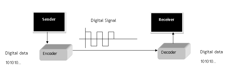
In this lesson, you will learn about various digital transmission coding scheme and understand that digital signals made it possible to encode digital information transmission. Our goal is to send digital information as digit signals.
Basics Components
The basic components of digital signal transmission are digital data and digital signals that are sent including the rate at which it is transmitted.
Data Rate = no of bits sent in one second is known as Bit rate.
Signal Rate = no of signal element sent in one second. It is also known as signal rate, baud rate or modulation rate.
R = Number of data element per signal element
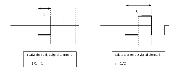
Relationship between data rate and signal rate is as follows.
S = c \times N \times\frac{1}{r} \hspace{1mm}baudsWhere C= case factor, N = Bit rate and r = data rate to signal rate ratio currently defined.
Not bit rate, but baud rate determines the bandwidth of the digital signal.
B_{min} = c \times N \times \frac{1}{r}Maximum data rate is given as
N_{max} = \frac{1}{c} \times B \times rBaseline wandering
The receiver calculates a running average of received signal power called the baseline. Baseline is used for determining the value of data elements. A long stream of 1 or 0 cause drift in the baseline and result in baseline wandering.
DC Components
Low frequencies close to zero (but not zero) due to constant voltage level in digital signal are called the DC component can cause problem in some system that cannot pass such low frequencies.
Self-Synchronization
Receiver bit interval must match with the sender bit interval; otherwise, receiver will misinterpret the signals.
This type of self-synchronized digital signal includes timing information with the signal.
Built-in-Error Detection
Some line coding schemes have built-in error detection scheme which is very helpful.
Immunity to Noise and Inference
Some line coding scheme has these characteristics to be immune to noise and inference.
Complexity
Complex line coding schemes are very difficult to interpret at the receiver end. Higher the signal level, more complex the line coding schemes will be.
Line Coding Schemes
There are many types of line coding schemes. The following figure shows different approach to line coding.
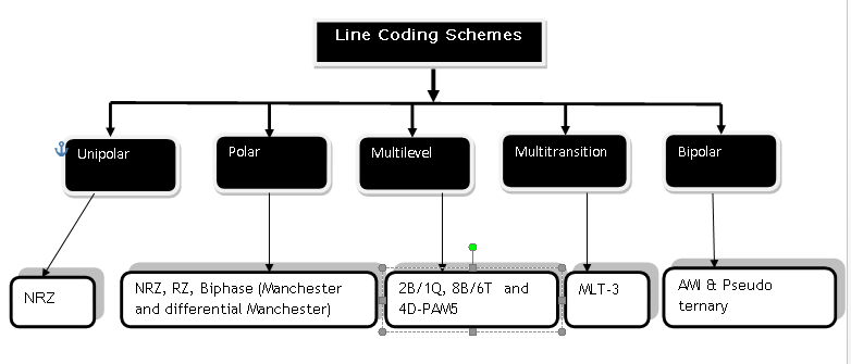
Unipolar Scheme
All signal level on one side.
Polar
Signal level on both side of the time axis,  can be positive and
  can be negative.
Bipolar Schemes
The signal uses  voltage levels:
  ,
,  and
and  .
.
Multilevel Schemes
The idea is to increase bits per baud by encoding  bit pattern to
  signal pattern.
Multitransition Schemes
It is a technique used in Manchester Coding with different transitions levels.
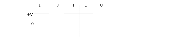
Unipolar Scheme – NRZ (Non-Return to Zero)
In Unipolar, NRZ scheme in which +ve voltage define bit 1 and zero voltage define bit 0. It is called NRZ because signal does not return to zero in the middle of the bit.
Polar Scheme – NRZ (Non-Return-to-Zero)
In polar scheme, the signal exists on both side of time axis. A voltage level for 0 can be +ve and voltage level for 1 can be –ve.
There are two types of NRZ in Polar scheme.
NRZ-L (NRZ –LEVEL) – The level of voltage determines the value of the bit.
NRZ-I (NRZ-Inverted) – Change or Lack of change in the voltage determines the value of bit, No change means bit value is and a change or transition means bit value 1.
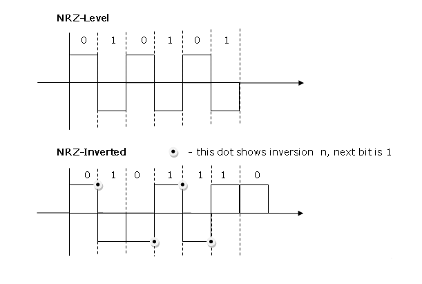
Baseline wandering is twice in NRZ-L compared to NRZ-I. It happens when a long sequence of 0s or 1s are encountered, the receiver has difficulty in computing the average signal. For NRZ-I, this is only when a long sequence of 0s happen.
NRZ-L has another problem of change in the polarity of the signal during transmission. For example, in a twisted pair cable, change in polarity will cause all 0s to 1s and all 1s to 0s.
NRZ-L and NRZ-I both have signal rate of N/2 Baud
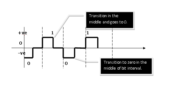
and have DC component problem.Polar – RZ (Return-to-Zero)
The signal changes in the middle of bit interval and goes to zero in RZ encoding. There are three levels – positive, negative and zero.
Since, it is using more level, more bandwidth is required and also this is complex mechanism, hence not used today. It is replaced with much efficient Manchester encoding.
Polar Biphase: Manchester and differential Manchester Coding
In Manchester coding, idea of RZ and NRZ-L is used for encoding. There is transition to next level in the middle of every bit and it gives synchronization.
References
- Andrew S. Tanenbaum, David Wetherall. n.d. Computer Networks. Pearson, 23-Jul-2013.
- Behrouz A. Forouzan, Sophia Chung Fegan. n.d. Data Communications and Networking, Fourth Edition. McGraw hill education.