Open Systems Interconnection (OSI) Model
Networking is a complex computation problem that includes several tasks. The underlying hardware cannot do all the tasks, so a software layer is required to prepare the message before hardware could send them as signals.
The hardware only knows electrical signals, but there are several layers of software all of which need standardization. You will learn the Open Systems Interconnection (OSI) model in the article.
The layered model that dominated the data communication and networking before 1990 was the Open Systems Interconnection (OSI) model. It was never fully implemented and TCP/IP became the dominant commercial architecture because it was tested extensively.
The OSI Model
The International Standards Organization (ISO) decides international standards. OSI is an ISO standard that covers all aspects of network communication. It is the model using with a flexible and interoperable network is designed. The main purpose of OSI is to enable communication without modifying underlying software or hardware infrastructure.
OSI model has 7 different layers which help in moving information from source to destination in a network.
- Physical Layer
- Data Link Layer
- Network Layer
- Transport Layer
- Session Layer
- Presentation Layer
- Application Layer
If a message is sent from A to B, it passes through many intermediate nodes. Each layer call service of layer below it. Layer 3 uses servics of layer 2, Layer 4 uses services of layer 3, and so on.
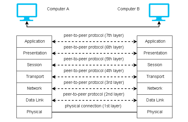
Layer 3 of A can talk to layer 3 of B. It communication is controlled by agreed rules called protocols. The processes on each layer communicating with different machines are called peer-to-peer processes and communication itself is peer-to-peer process controlled by protocols in a given layer.
Peer-To-Peer Processes
Each layer adds its own information to the message it receives from the layer above it. At layer 1 the packet is converted into a form that can be transmitted to a receiving device.
At the destination, the packet is unwrapped by each layer and pass the rest to a layer above it until the user get the original message.
For example, layer 2 unwrap the information and passes it to layer 3, layer 3 unwraps the information meant for it and passes the rest to the layer 4 and so on.
Interface Between Layers
The adjacent layers in OSI model communicate to each other user interface for layers. The interface defines the information and services a layer must provide to a layer above it.
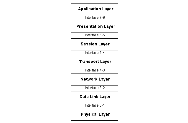
Well-defined interfaces and layer functions provide modularity to a network. It is then easy to change or replace a layer of functions without changing other layers.
Organization of the Layer
We have discussed each layer in the next section, but you can organize 7 layers into 3 subgroups :
-Layer 1, 2 and 3 (Network support layer).
It deals with physical connections, physical addressing, and transport reliability and timing.
-Layer 5,6 and 7 (User support layers)
It allows interoperability among unrelated software systems.
-Layer 4 (Transport Layer)
This layer is a link between two subgroups – network and user support layer – ensuring the end-to-end transmission of data. The upper layer information is software, but the lower layer has hardware and some software components. The transport layer ensures that the lower layer transmits information in the correct form provided by the upper layer.
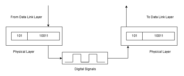
Physical Layer
The physical layer is responsible for the transmission of the bit stream to the next node in the network. It contains mechanical and electrical specifications for the interface and the transmission medium. It defines the procedures and functions for interfaces and physical devices to transmit the data.
A physical layer is concerned with the following:
- Representation of Bits – It has streams of bits only, which is encoded into signals -electrical or optical. It defines the type of encoding.
- Physical characteristics of interface and medium – It defines the transmission medium and the interface between devices and transmission medium.
- Data rate – The number of bits per second is controlled by the physical layer.
- Synchronization of Bits – Sender and receiver must be in sync at the bit level. Their clock must be synchronized.
- Line configuration – This is concerned with the type of connection – point-to-point or multipoint link.
- Physical topology – Physical layer how devices are connected to the network and what is the topology – mesh, star, ring, or bus.
- Transmission mode – It defines the direction of the communication – half-duplex or full-duplex.
Data Link-Layer
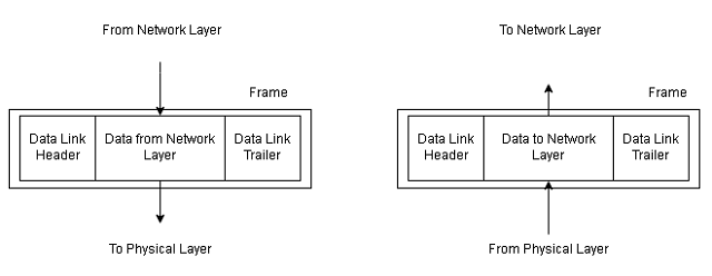
The data link layer converts the bit stream from physical layer into a reliable link by making it error-free for upper layers. It is responsible for moving data frames from one node to the next (hop-to-hop delivery) in the network.
The other responsibilities of the data link layer include:
- Framing – A stream of bits from network layer is converted into a unit called frame by data link layer.
- Physical Addressing – The data link layer provides 12 digit address of the destination in the frame.
- Flow control – The data rate of sender is faster than data rate at which receiver consumes the information. The data link layer impose flow control to avoid sending too much information to the receiver.
- Error control – The data link layer detects and retransmits lost or damaged frames during transmission. It removes any duplicate frames from getting delivered.
- Access control – If more devices are connected to same link, the link layer protocols determine which device have the control over the link at a given time.
Network Layer
This layer is responsible for source-to-destination delivery of packets, sometimes accross multiple networks or links. If two systems are connected to same network, the data link layer is enough to deliver the packets, no need for a networking layer.
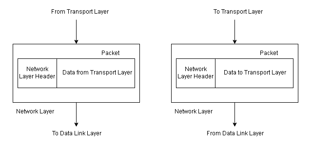
Two systems are on different networks connected with devices between the networks. The network layer is necessary for source-to-destination delivery.
The responsibilities of the network layer are:
- Logical addressing – If packet sent to a different network, the network layer adds a header from upper layer containing logical address of sender and receiver.
- Routing – Independent networks form an internetwork connected through routers or switches to route or switch the packets to the destination. The network layer provides routing mechanisms.
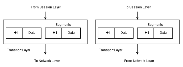
Transport Layer
The transport layer responsible for process-to-process delivery of packets. The process is a running application program. The network layer does not recognize the packets as a complete message, but it treats them as independent units. The transport layer makes sure that the whole message is delivered without loss and in order at the destination.
Basically, it does the flow control and error control at the source-to-destination level.
Other responsibilities of the transport layer are:
- Service-Point addressing – The end to end delivery means delivery of packets from one process to another process at the destination. The packet contains transport layer header that includes a server-point address or port address.
- Segmentation and reassembly – A message is divided into segments and each segmentcontains a sequence number. The number enables the transport layer at the destination to reassemble the message correctly and replace packets that are lost in transmission.
- Connection control – Transport layer could be connectionless or connection oriented.Connectionless transport layer treat packets as independent entity and do not account for loss of packets. The connection-oriented transport layer establish a connection with the destination and retransmit the lost packets. Once the message is delivered, the connectionis terminated.
- Flow control – The transport layer performs flow control just like data link layer, but this layer does it end-to-end, rather than a link.
- Error control – Error control is performed process to process. Error control is achived through retransmission.
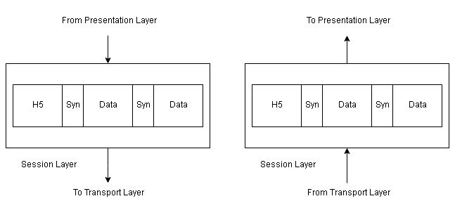
Session Layer
The session layer is network dialog controller which establish, maintain and synchronize the communicating systems.
Responsibilities of the session layer are:
- Dialog control – It allows the communication to be half-duplex or full-duplex.
- Synchronization – It allows a process to add checkpoints, or synchronization points to a stream of data. If 2000 pages are sent then checkpoint after every 100 page is advisable. When a network crash happens at page 543 with a check point at 500. The network requires to retransmit pages only from 501 to 543.
Presentation Layer
This layer is for syntax and semantics of the information exchanged between communicating systems.
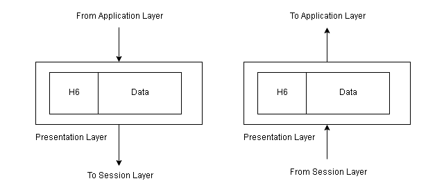
Responsibilities of presentation layer are:
- Translation – The presentation layer is responsible for interoperability between different encoding systems. The sender data is changed to common format and at the destination, presentation layer changes it to receiver format.
- Encryption – Encrypt original information to encrypted format and at the destination, presentation layer decrypt the message into original form.
- Compression – Reduce the number of bits in the information.
Application Layer
It enables users or software applications to access the network. It provides interfaces and services like email, remote file transfer, shared databases, and other types of distributed computing services.
Responsibilities of the application layer are:
- Network virtual terminal – It is software version of a physical terminal that allows users to log on to a remote host. It creates a software emulation of a terminal at remote host to which user’s computer talk to and help user log on. It is a software application.
- File transfer, access, and management – Allows to access files , read or change files, and transfer from a remote computer. It is a software application.
- Mail services – Application to store email storage and forwarding.
- Directory services – Provides access to distributed database sources and access for global information about various objects and services.
Tracert Command in Windows
The tracert command is a built-in networking tool that finds all the hops between localhost (where you run the command) and the destination computer on the network.
In this exercise, you will learn to use basic tracert command. For the purpose of the exercise, we are using a Windows 7 64-bit machine.
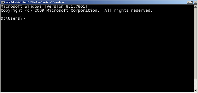
Step 1: Open command prompt
To open a command prompt in Windows XP, go to start > click run > type cmd. In Windows 7, type cmd in the search box, then click cmd.exe. A black window will open as shown in the following figure.
Step 2: Find or traceroute to google.com
In this step, we will use trace route command or tracert command to find all the hops between our computer and google.com.
Type following command in command prompt.
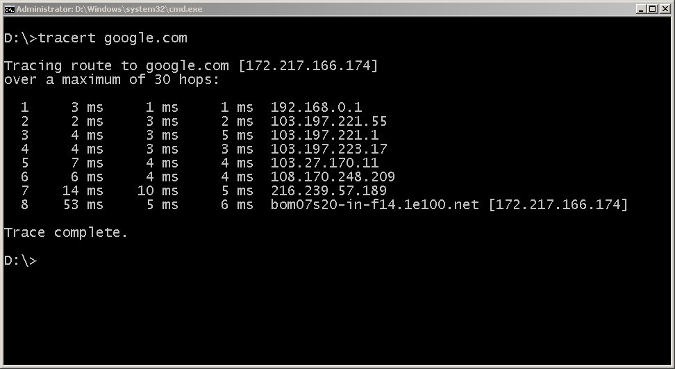
tracert google.com
The following result displays all the hop with IP address between localhost and google web server (google.com)
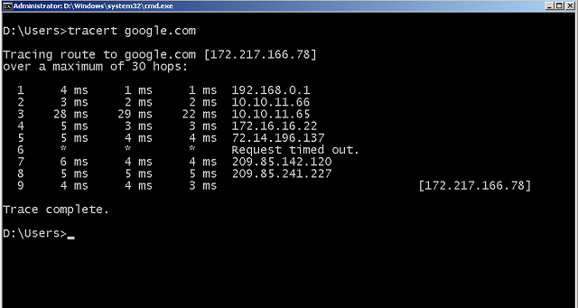
The trace completed successfully. All the hops are listed properly, if there was a problem, then the command will show the error.
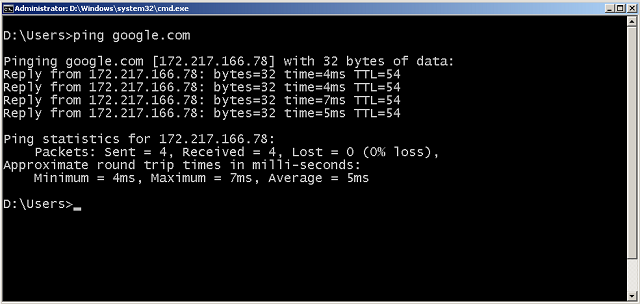
Ping Command in Windows
A ping is a built-in tool in the Microsoft Windows operating system. You can use it to test network connectivity with a remote host or computer.
If you have a windows computer try this on your own.
The localhost is the same computer where you are running the ping command. We need first to check local computer network device.
Step 1: Open the command prompt
Go to start > all programs > cmd, if you have windows prior to Vista or 7. You should see the command prompt. Otherwise, type in search box cmd and click in cmd.exe the search results.

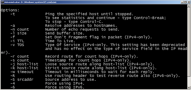
Step 2: Check if the ping is available
You should check if the ping is available on your computer or not. Type ping -help or ping -h to get help with ping. If you get some results then the ping is installed, else windows will not recognize the command.
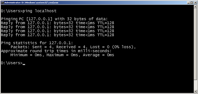
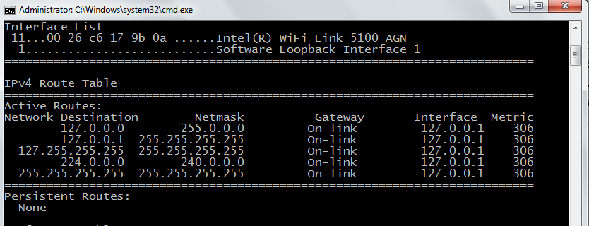
Step 3: Type ping localhost to check local computer networking ability.
Type the command – ping localhost and enter. If the network is working correctly, you should see the following results.
Step 4: Test connectivity for a remote host
Now that we know the localhost is working. You need to test connectivity with a remote computer or server. You can do this by typing the ipv4 address or domain name(internet name) of the remote computer.
ping 172.217.166.78 or ping google.com will result in failure or return response shown in the next figure.
In the next exercise, you will learn about another tool called.tracert
Network Categories
Networks are made of many types of equipment and technologies, therefore, it follows two popular standards – the OSI model and Internet Model. A network fall under 3 different categories – LAN, WAN, and MAN.
Before we jump into the computer models, know that computer networks fall under certain categories depending on their geographical size.
Local Area Network (LAN)
A local area network (LAN) is a privately owned network that links offices, a building, or a campus. The LAN is limited to a few kilometers. It can be a simple network with 2 computers and a printer or it can span an entire company with computers that has audio/video peripherals.
LANs are used for resource sharing among PCs, that shared printer(hardware) or software (application). Another model is the client-server model where a single computer with more disk space configured to be server and other computers in LAN are clients. The network is restricted due to license by a user per software installation or user licensed by access to OS.
LAN uses special types of transmission medium and topology such as bus, ring, and star. Speed of LAN nowadays has increased to 100 Mbps to 1 Gbps.
Wide Area Network
Wide Area Network (WAN) performs long-distance transmission of data over large geographical areas such as countries, continents, and the whole world.
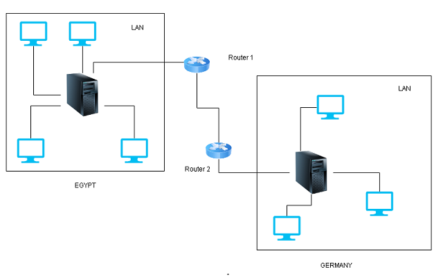
There are two types of WAN network – Switched WAN and point-to-point WAN. The switched WAN connects two networks with a router. One of the networks (LAN or WAN) connects to another LAN or WAN system. The point-to-point WAN is a lease-line that connects a LAN or a home computer to an internet service provider (isp) who provides internet access.
Metropolitan Area Network (MAN)
This spans a few kilometers between LAN and WAN networks. The MAN covers a city or a town. For example, telephone companies that provide high-speed DSL line for the internet to their customers use MAN. Cable TV originally intended for tv is used for internet connection is a MAN network.
Network Topology
A topology is the physical structure of the network using different types of connection. In this article, you will learn about network topologies such as mesh, star, ring, and bus topology.
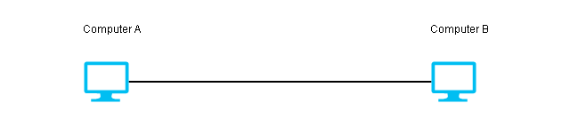
A network is two or more devices connected through links where the link transfers data from one device to another.
The link connects the devices and they are of two types:
Point-to-point connection
This type of connection has a dedicated link between two devices. The devices use the entire capacity of the link.
Example,
TV remote control use infrared to control TV.
Multipoint or Multidrop connection
More than two devices are connected to the link. The capacity of the link is either spatially shared(simultaneously connected) or time-shared (take a turn to use the link).
Network Topologies
A network topology defines the physical structure of the network. Here is a list of network topologies.
1. Mesh
2. Star
3. Bus
4. Ring
5. Hybrid
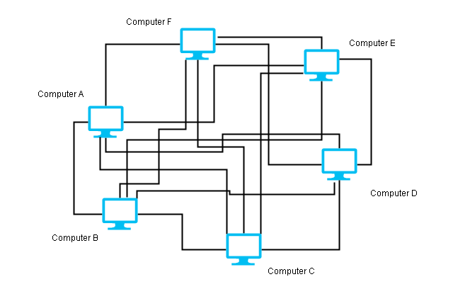
Mesh Topology
The mesh topology consists of a point-to-point connection between every device using a dedicated link. If there are n nodes in the network, then it makes n (n-1) / 2 duplex links.
Advantages
- If one link fails in a mesh that will not cause the whole network failure. Only that link is affected.
- The point-to-point connection makes fault identification easier and ensures the proper delivery of the packets.
Disadvantages
- The mesh network uses too many ports that make it expensive.
- Too many cables make it difficult to implement this network, therefore, a mesh is only required when the network is closed or requires high availability. Example, telephone regional offices are connected through the mesh.
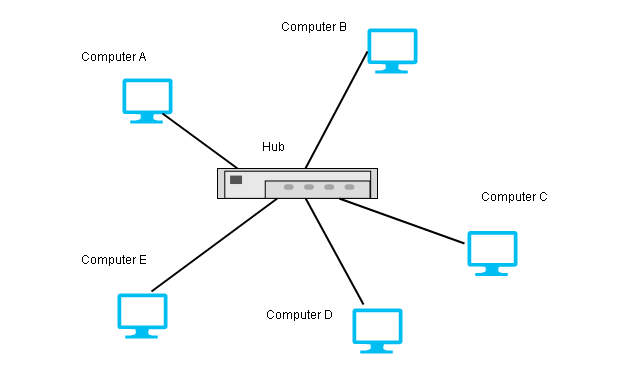
Star Topology
The star topology makes a point-to-point connection to a hub device. The hub exchange data on behalf of the devices.
Advantages
The star topology is not expensive because of less number of cables and ports required as compared to mesh.
A failure of one link in star topology does not fail the whole network. Only that link is failed.
The number of ports on devices is also less as compared with a mesh topology.
Disadvantage
If the hub device goes down or becomes faulty, the entire network goes down.
Example,
This type of topology is used in LAN (Local Area Network).
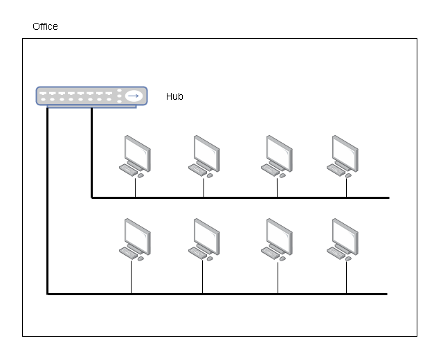
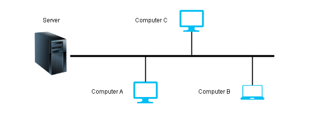
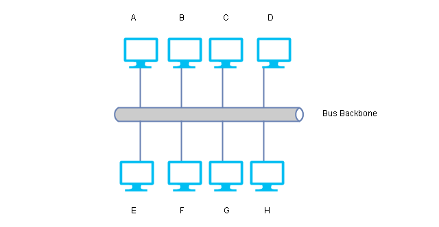
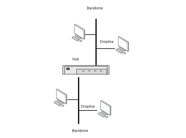
Bus Topology
The bus topology uses a multipoint connection, and all devices are connected to a backbone link in the network. The backbone is one long cable to which nodes are connected using droplines and taps. A dropline is a connection between the device and the backbone. A Tap is a connector that creates contact with the metallic core of the backbone.
Advantages
- A bus topology is easy to install. It uses less cabling because only backbone and droplines are required.
- A new device installation requires changing backbone because it may not be of sufficient length.
Disadvantages
- The backbone signals become weaker and weaker towards the other end of the cable as it travels some distance.
- There is a limit to the number of devices a bus topology can support due to backbone capacity.
- Failure at any point in the network can cause complete failure of the network.
- Fault isolation is difficult.
Example, early LANs were bus topology networks.
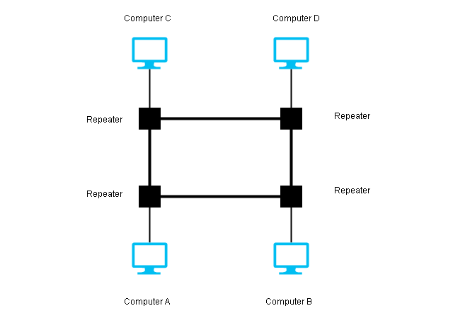
Ring Topology
A ring topology appears like a ring where a single device is connected using point-to-point on either side. A single pass from one direction in the ring until it reaches its destination.
Each device has a repeater, if the message intended for another device, then the repeater regenrates it and passes it to the next device. Otherwise, it accepts it.
Advantages
- Easy installation and fewer cables.
- In a ring topology, fault isolation is easy. When a repeater not working an alarm can alert a network administrator with a location.
- Adding new device is easy because you only need two connections on either side of the device.
Disadvantages
- The only difficulty with ring topology is that a single device failure can cause the whole network to go down.
Hybrid Topology
A hybrid topology is made of a combination of two or more network topologies.
Consider the above example, star topology and each connection of star can be a bus network.
Computer Network Basics
Computer networks are a form of a data communication system where data refers to information in an agreeable form for parties sharing and using them.
What is Data Communication?
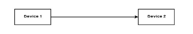
Data communication itself is an exchange of data between two devices over a medium such as a cable wire. The devices that are part of communication must have the necessary hardware and software to complete the communication.
The effectiveness of data communication depends on:
- Delivery
- Accuracy
- Timeliness
- Jitter
Delivery
The data must get delivered to the correct destination.
Accuracy
The data must be accurate when it arrives at the destination device. Inaccurate data is of no use.
Timeliness
There is no use of the data that is delayed. Therefore, it must be delivered in a timely manner.
Jitter
Jitter happens when audio and video arrive at the destination at different time. There is a never delay in delivery of the packets.
What are the important components of data communication?
The data communication involves certain components that work together to complete the communication process. They are:
- Message
- Sender
- Receiver
- Communication Medium
- Protocol
Message
The message is the information that the sender share with the receiver over a communication medium.
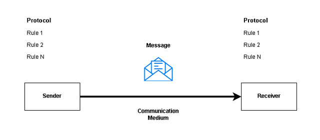
Sender
A sender is the source of the message who is responsible for creating and sending the message to a receiver.
Receiver
A receiver is a destination for the message over a communication medium.
Communication Medium
A communication medium is a link between sender and receiver. Wired and Wireless medium are two types of communication mediums available to us.
Protocol
The protocol is a set of rules for communication. This is one of the most important features of the data communication system. The protocol must be same for both sender and receiver otherwise communication will fail.
How to represent data?
You have learned that the purpose of data communication in a network is to send and receive messages. There are many forms of data available.
- Text
- Images
- Numbers
- Audio
- Video
Text
The text is the most common method of sharing information. A message in text form could be email, chat, or a webpage, or a word processor file. Textual information is made of ASCII alphabet characters or uses UTF-8 characters.
Images
The images are visual information. It could be a digital photograph, vector, or any illustration. Images are displayed in computers in pixels or line drawings. The pixel decides the resolution of the image, if a sender sends a higher resolution image, the receiver must have the ability to show the same resolution, otherwise, the most suitable resolution is selected for the image.
Numbers
The numbers are ANSII characters that start from 0 to 9. The numbers are important to represent numeric information such as financial data or some statistics.
Audio
Audio is broadcasted over the network or sent as a recorded message to receivers. Audio files are of many forms such as mp3, aac, etc. These files could be listened to with any audio player.
Audio information can be broadcasted over a wireless or wired medium to more than one receiver. For example, radio is a very popular medium, telephones are a common audio device to speak directly.
Video
A video is moving visual information. Unlike images, the video is recorded and sent or broadcasted like audio over a network. The computer saves video information in the form of mp4, MPEG, mkv, etc files.
Data flow in Communication
The data communication between the sender and the receiver has direction in some communication systems. They are:
- Simplex
- Half-Duplex
- Full-Duplex
Simplex
In the simplex type, data communication happens only one direction. For example, the radio broadcast where the receiver can only listen to the audio.
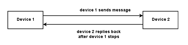
Half-Duplex
The half-duplex is two-way communication with data flowing in either direction at a time. Walkie-Talkie communication is a half-duplex communication with one person talking on either side at a time.
Full Duplex
The full duplex communication gives the ability to communicate two way all the time. All modern communication devices have this ability.
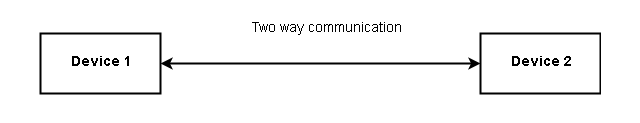
For example, a mobile phone is a popular medium of communication.
Network Layer – Understanding Packet Delivery and Routing
In this lesson, you will learn about Network layer and its role in delivery, forwarding and routing in a network. You must be familiar with all the layer of OSI and TCP/IP to understand this article, because in computer networks, each layer affect each other during communication.
Delivery of Packet
Network layer supervises the handling of packets by underlying physical networks. We call it delivery of packets to destination. Delivery of packets to final destination is done it two ways.
- Direct – when the destination is in the same physical network or delivery between last router and destination.
- Indirect – packet goes from router to router until it reaches the one which is connected to same physical network as the destination.
Forwarding of packet
Forwarding means placing the packet in its route to destination and it requires a Routing table. All routes for a routing device is available in the routing table.
Forwarding techniques
- Next Hop method vs. routing method
In this method, the routing table contains only address of next hop instead of information about the complete route as in routing method.
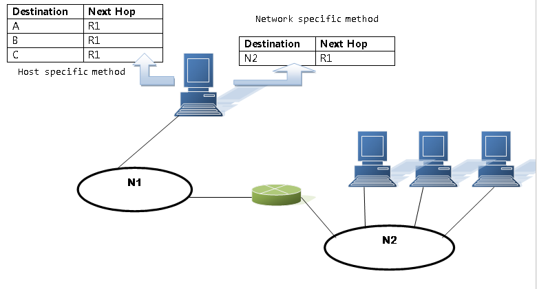
- Network specific method vs. Host specific method
In this method, we reduce the size of routing table by replacing every host address on the same network by a single network address.
Where in Host Specific method, information about every host is included in the routing table.
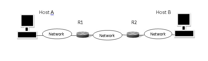
Routing table of Host A based on route method
| Destination | Route |
| Host B | R1, R2, Host B |
| Host B | R2, Host B |
| Host B | Host B |
Routing table of Host A based on next hop method
| Destination | Route |
| Host B | R1 |
| Host B | R2 |
| Host B | —– |
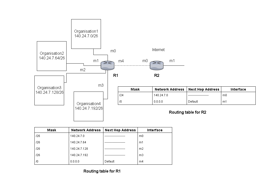
Forwarding Process
When the packet arrives it has a destination address which is not enough to locate the network of destination host. The routing table needs at least 4 field to find the network address of the destination, in classless addressing.
| Mask (/n) | Network Address | Next hop address | Interface |
| /26 | 180.70.65.192 | — | M2 |
| /25 | 180.70.65.128 | — | M0 |
| /24 | 201.4.22.0 | — | M3 |
For example: suppose a packet came with destination address 180.70.65.140 and is compared with different subnet mask. If the result is a network address in the table, then forwarding happen to that address.
| 1011 0100 | 0100 0110 | 0100 0001 | 1000 1100 |
180 70 65 140
| 1111 1111 | 1111 1111 | 1111 1111 | 1000 0000 |
= /25
If AND both mask and destination address, we get
| 1011 0100 | 0100 0110 | 0100 0001 | 1000 0000 |
180 70 65 128
The packet is routed to 180.70.65.128/25 in this way.
Address Aggregation
Classless addressing increases the size of the routing table because it divides the address space into many blocks.More the entry , more time required for searching the table. Address aggregation assign a common address for a block of address if the it is possible to combine the block of address, otherwise not.
Longest mask matching
The routing table entries are arranged in order where longest mask comes at top. Suppose we have /24, /26 and /27 . The first comes the /27, /26 and then /24 and so on.
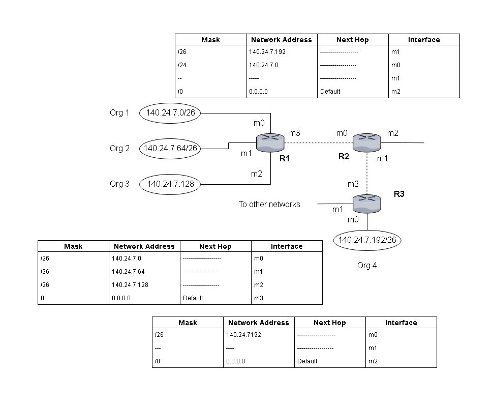
Suppose a packet that arrive for destination 140.24.7.200 , then it will be ANDed with /26 and result will be 140.24.7.192 , but if the same address gets ANDed with some other mask , it will get routed to some other router.
Hierarchical Routing
In hierarchical routing, National ISPs have a block of address different from regional ISP address, and local ISP. All of them share a common ipaddress, but using the classless addressing scheme the addresses are subdivided into blocks at each level. Local ISP have a.b.c.d/m as common address , then it will have a block of address x.y.z.v/n as addresses.
Suppose 120.14.64.0/23 means 32-23 = 9
It means there is block size of 29 = 512 addresses.
At each level classless addressing is used and network is divided into blocks of addresses.
Routing table
A routing table is either static or dynamic. In this section we discuss both routing tables.
Static routing table
A static routing table contains information entered manually. When there is a change in the network it does not get updated automatically, administrator has to enter them manually. It can be used in a small internet or experimental internet where we do not have lot of changes.
Dynamic Routing table
A dynamic routing table is updated periodically by one of it’s routing protocol such as RIP, OSPF or BGP. The table gets updated automatically whenever there is a change in the internet hence it is suitable for big internet.
Format of routing table
| Mask | Network Address | Next-hop Address | Interface | Flags | Reference count | Use |
| ——– | ——– | ——– | ——– | ——– | ——– | ——– |
- Mask – mask applied for the entry
- Network Address – network address or host address of the destination.
- Next-hop Address – address of next-hop router.
- Interface – name of the interface
- Flags – It is on/off flag that shows presence or absence. There are 5 flags
- U(up) – router is up and running.
- G(gateway) – destination is another network.
- H(host-specific) – entry in network address is host-specific.
- D(added by redirection) – added by redirection msg from ICMP.
- M(modified by redirection) – modified by redirection msg from ICMP.
Tools /Utilities – Packet Deliver and Routing
There are few important tool which is frequently used to check routing configuration or troubleshooting. These are the most popular ones and available with most of the system by default.
NETSTAT
Netstat is very popular tool among IT people. There are many switches that will tell you a lot about the host and the network.
IPCONFIG
The ipconfig is the default networking utility for finding ip related information on the host. You can use ipconfig /all, ipconfig/ renew to get new ipaddress and ipconfig /flushdns to clear dns cache.
TRACERT UTILITY
Tracert is a special utility that display all hop between the local host( computer) and destination ( google.com) in this example.
References
Andrew S. Tanenbaum, David Wetherall. n.d. Computer Networks. Pearson, 23-Jul-2013.
Behrouz A. Forouzan, Sophia Chung Fegan. n.d. Data Communications and Networking, Fourth Edition. mcgraw hill education.
Find (TCP and UDP) Services and Port Numbers on Windows
This is a practical exercise for the computer network. In this article, you will find the services and port numbers for both UDP and TCP. You need an any Windows XP and above, up to Windows 7 to perform this exercise. Our goal for the exercise is to find the list of TCP and UDP services and port number on Windows computer.
This exercise is performed on a Windows 7 64-bit computer, for some high version windows such as Windows 10, the steps may be different.
The list of steps required to do this lab is as follows. Do not modify any files, otherwise, it will be fatal for your computer.
1. Open My Computer | Computer
2. Go to C:/ drive
3. Open Windows/System32/Drivers/etc
4. Open Services with Notepad.
5. View the Service name, Port/<UDP>|<TCP>
6. Self – Analyze your findings.
We will perform each of these steps and verify the contents of the Services File.
Step 1:
On a Windows 7 computer, click on Start.
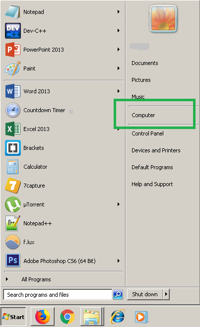
You need to click Computer, and it will open and show your drives.
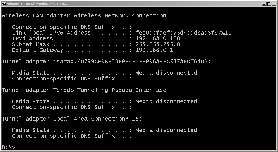
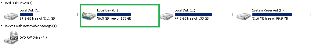
Step 2:
Open the drive that has Windows folder. This is normally the C:/ drive, but in this example, we have it installed on D:/ drive.
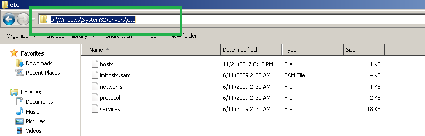
Step 3:
Now that you have found Windows folder under C:/ or D:/ drive, go to D:/Windows/System32/Drivers/etc.
Step 4:
The next step is to open the Services file using Notepad program. You do not have to install Notepad, its builtin software on windows.
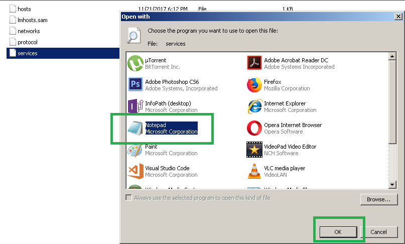
When you try to open the file, you may get a dialog box like the one shown above. Select Notepad and Click OK to complete.
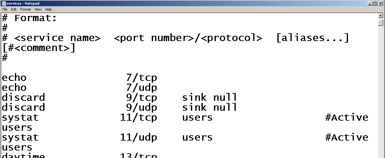
Step 5:
You will find a list of (TCP and UDP) services and port numbers supported by windows. Every windows computer has this registered ports and protocols, you will learn about these networking protocols and ports in our computer network tutorial.
The UDP and TCP protocols with port and an IP address make a network socket, which connects your computer to a network and start the communication. In other words, there is no socket, there is no network communication.
Digital Transmission
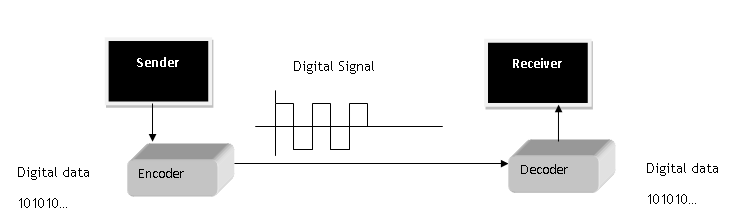
In this lesson, you will learn about various digital transmission coding scheme and understand that digital signals made it possible to encode digital information transmission. Our goal is to send digital information as digit signals.
Basics Components
The basic components of digital signal transmission are digital data and digital signals that are sent including the rate at which it is transmitted.
Data Rate = no of bits sent in one second is known as Bit rate.
Signal Rate = no of signal element sent in one second. It is also known as signal rate, baud rate or modulation rate.
R = Number of data element per signal element
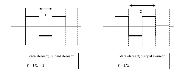
Relationship between data rate and signal rate is as follows.
S = c \times N \times\frac{1}{r} \hspace{1mm}baudsWhere C= case factor, N = Bit rate and r = data rate to signal rate ratio currently defined.
Not bit rate, but baud rate determines the bandwidth of the digital signal.
B_{min} = c \times N \times \frac{1}{r}Maximum data rate is given as
N_{max} = \frac{1}{c} \times B \times rBaseline wandering
The receiver calculates a running average of received signal power called the baseline. Baseline is used for determining the value of data elements. A long stream of 1 or 0 cause drift in the baseline and result in baseline wandering.
DC Components
Low frequencies close to zero (but not zero) due to constant voltage level in digital signal are called the DC component can cause problem in some system that cannot pass such low frequencies.
Self-Synchronization
Receiver bit interval must match with the sender bit interval; otherwise, receiver will misinterpret the signals.
This type of self-synchronized digital signal includes timing information with the signal.
Built-in-Error Detection
Some line coding schemes have built-in error detection scheme which is very helpful.
Immunity to Noise and Inference
Some line coding scheme has these characteristics to be immune to noise and inference.
Complexity
Complex line coding schemes are very difficult to interpret at the receiver end. Higher the signal level, more complex the line coding schemes will be.
Line Coding Schemes
There are many types of line coding schemes. The following figure shows different approach to line coding.
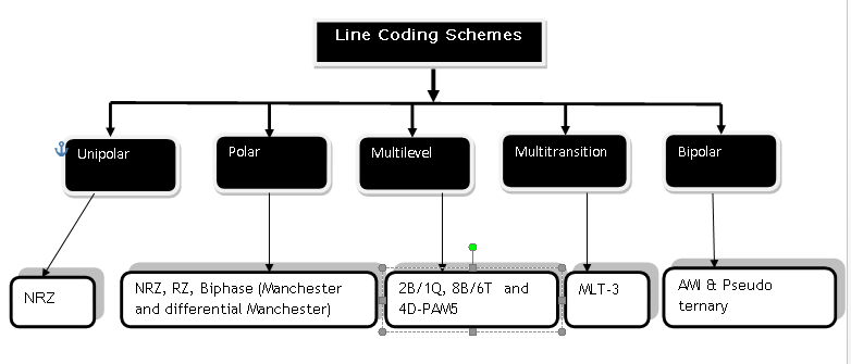
Unipolar Scheme
All signal level on one side.
Polar
Signal level on both side of the time axis,  can be positive and
  can be negative.
Bipolar Schemes
The signal uses  voltage levels:
  ,
,  and
and  .
.
Multilevel Schemes
The idea is to increase bits per baud by encoding  bit pattern to
  signal pattern.
Multitransition Schemes
It is a technique used in Manchester Coding with different transitions levels.
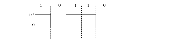
Unipolar Scheme – NRZ (Non-Return to Zero)
In Unipolar, NRZ scheme in which +ve voltage define bit 1 and zero voltage define bit 0. It is called NRZ because signal does not return to zero in the middle of the bit.
Polar Scheme – NRZ (Non-Return-to-Zero)
In polar scheme, the signal exists on both side of time axis. A voltage level for 0 can be +ve and voltage level for 1 can be –ve.
There are two types of NRZ in Polar scheme.
NRZ-L (NRZ –LEVEL) – The level of voltage determines the value of the bit.
NRZ-I (NRZ-Inverted) – Change or Lack of change in the voltage determines the value of bit, No change means bit value is and a change or transition means bit value 1.
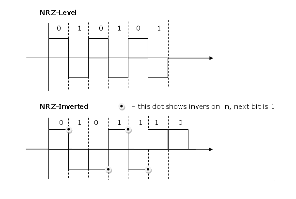
Baseline wandering is twice in NRZ-L compared to NRZ-I. It happens when a long sequence of 0s or 1s are encountered, the receiver has difficulty in computing the average signal. For NRZ-I, this is only when a long sequence of 0s happen.
NRZ-L has another problem of change in the polarity of the signal during transmission. For example, in a twisted pair cable, change in polarity will cause all 0s to 1s and all 1s to 0s.
NRZ-L and NRZ-I both have signal rate of N/2 Baud
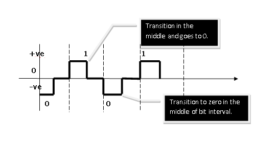
and have DC component problem.Polar – RZ (Return-to-Zero)
The signal changes in the middle of bit interval and goes to zero in RZ encoding. There are three levels – positive, negative and zero.
Since, it is using more level, more bandwidth is required and also this is complex mechanism, hence not used today. It is replaced with much efficient Manchester encoding.
Polar Biphase: Manchester and differential Manchester Coding
In Manchester coding, idea of RZ and NRZ-L is used for encoding. There is transition to next level in the middle of every bit and it gives synchronization.
References
- Andrew S. Tanenbaum, David Wetherall. n.d. Computer Networks. Pearson, 23-Jul-2013.
- Behrouz A. Forouzan, Sophia Chung Fegan. n.d. Data Communications and Networking, Fourth Edition. McGraw hill education.
Network Layer – Logical Addressing
In this lesson, you will learn about logical addressing scheme of networking layer, this layer deals with ipadderessing and has a class based and class addressing scheme. You will also learn concept of sub netting and super netting.
IPv4 addresses
An IPv4 address is  bit address that uniquely and universally defines the connection of a device.
Unique means no two devices can have same address at the same time on Internet.
Address Space
An address space is the total number of addresses used by IPv4 protocol. If  bit address is used, the total addresses in the address space will be
 .
.
IPv4 uses  bit addresses then the total number of addresses in the address space is
\begin{aligned}
2^{32} = 42, 94,967,296
\end{aligned}
Notations
Binary Notation: 
Decimal Notation: 
Each of the octet range to  .
.
Classful addressing
In classful addressing, the address space is divided in to  classes:
  and
and  .
.
Binary Notation starting bits of first octet will tell the class.
| Class | First Octet | Second octet | Third octet | Fourth octet |
 | | Any | Any | Any |
 |  | Any | Any | Any |
 |  | Any | Any | Any |
 |  | Any | Any | any |
|  | Any | Any | any |
In decimal notation, range of first octet tells the class to which the address belongs.
| Class | First Octet | Second octet | Third octet | Fourth octet |
|  | |||
|  | |||
|  | |||
|  | |||
|  |
Classes and Blocks
Each of the class is divided into fixed number of blocks and each block has a fixed size.
| Class | Number of Blocks | Block Size | Application |
|  |  | Unicast |
|  |  | Unicast |
|  |  | Unicast |
| |  | Multicast |
| | | Reserved |
There is flaw with this classful addressing. Class is used by large organization with large number of hosts and routers, but it’s too big for any organization. Class for mid size organization, but this also too big for organization leading to waste of ipaddress.
Class is too small for organizations.
So, in classful addressing,
a large part of addresses was wasted.
Netid, Hostid and Mask
In classful logical addressing, the address is divided into two parts – Netid and hosted
For example, Class address, the first byte is network id and the rest  bytes are Hostid.
| Class | Binary | Dotted-Decimal | CIDR |
|  |  |  |
|  |  |  |
|  |  |  |
Default mask help us find the Netid and hosted of an ipaddress.
The class in the form  is called CIDR (Classless Inter Domain Routing) which is used for classless logical addressing.
Subnetting
Classful logical addressing is obsolete now. An organization would get large number of class  or Class address and then these address would be subnetted means assign in logical groups to small networks called Subnets.
Supernetting
Large number of addresses of class and were depleted. To create a larger network, organizations combined class address into one group called Supernets and process is known as Supernetting.
Classful Addressing is not obsolete,
is replaced with Classless addressing.
Classless Addressing
Due to depletion of addresses, classless logical addressing was introduced to connect more organizations to the Internet.
Address blocks and Restrictions
In classless logical addressing, size of the address block depends on size and nature of the entity. For example,  may get thousands of address; home user may get
 addresses. To manage ipaddress, three restrictions were imposed
- Address in a block must be contagious
- Number of address in the block must be power of
 .
. - The first address must be evenly divisible by the number of addresses.
 .
. – first
 addresses
 – last
 – first
 addresses
 – last
Condition 1: address must be contagious .It is contagious.
Condition 2: The number of addresses is  .
.
Condition 3: first address when converted to decimal is divisible by  .
.
\frac{3,412,334,368}{16}=213270898How to convert ipaddress to decimal equivalent?
\begin{aligned}
&129.15.14 .17\\ \\
&256^3 \times 129 + 256^2 \times 15 + 256^1 \times 14 + 2560 \times 17\\ \\
&= 16777216 \times129 + 65536 \times15 + 256 \times 14\\ \\
&= 216420864 + 983040 + 3584 + 17\\ \\
&= 217407505
\end{aligned}
Mask
In IPv4 addressing, a block of addresses can be defined as  ,
,
In which  defines one of the addresses and the
 defines the mask.
notation defines first address, last address and the number of addresses.
Network addresses
An ipaddress has network address of which we need to find the first and last address for two reasons – first address is address of routing or hub device and last address gives the total size of a block of addresses.
First address in the block can be found by setting rightmost 32-n bits to 0s.
The last address in the block can be found by setting rightmost bit to 1s.
e.g.  is the address in a block. Find the first address and the last address.
Solution:
First address
\begin{aligned}
&1100 1101. 0001 0000. 00100101. 0010 0101\\ \\

&32 – 28 = 4 \hspace{1mm}bit\\ \\

&1100 1101. 0001 0000. 00100101. 0010 0000\\ \\

&205.16.37.16/32 \hspace{1mm} is \hspace{1mm} the \hspace{1mm} first \hspace{1mm} address.

\end{aligned}
Last Address
\begin{aligned}
&1100 1101. 0001 0000. 00100101. 0010 0101\\ \\
&32 – 28 = 4 \hspace{1mm} bit\\ \\
&1100 1101. 0001 0000. 00100101. 0010 1111 = 205.16.37.47/28\\ \\
&The \hspace{1mm} number \hspace{1mm}  of  \hspace{1mm} address  \hspace{1mm} in  \hspace{1mm} the  \hspace{1mm} block \hspace{1mm}  can \hspace{1mm}  \\ \\ &be  \hspace{1mm} found \hspace{1mm}  by \hspace{1mm}  using  \hspace{1mm} formula, \hspace{1mm} 2^{32-n}.
\end{aligned}IInd Method
Another method of finding the first address is ANDing ipaddress with subnet mask in binary notation.
\begin{aligned}
&11111111. 11111111.11111111. 11110000\\ \\
&1100 1101. 00010000.00100101. 00100101\\
&-----------------\\
&11001101 00010000 00100101 00100000 -> 205.16.27.32

\end{aligned}
The last address can be found by ORing any address in the block by complement of the mask.
\begin{aligned}
&00000000. 00000000. 00000000.00001111\\\\
&1100 1101.00010000.00100101. 00100101\\
&-----------------\\
&11001101. 00010000. 00100101. 00101111 -> 205.16.27.47/28
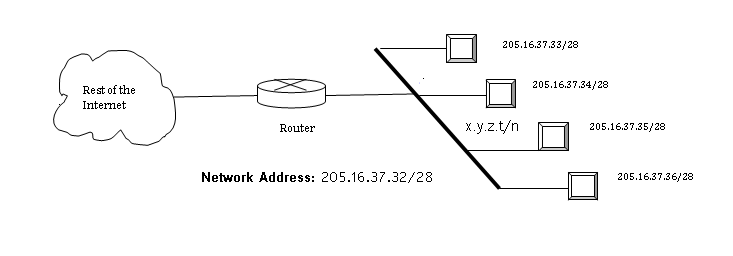
\end{aligned}Network Addresses in Logical Addressing
When an organization is given group of network addresses, then it is free to assign the address to any number of devices that want to connect to internet.
The first address is network address and used in the router and identifies the network in Internet
Hierarchy – Logical Addressing
Two level hierarchy: no sub netting
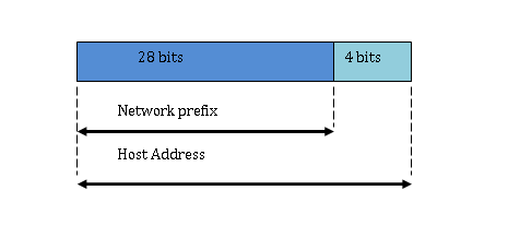
Each ipaddress in the block has two level hierarchy structure, the leftmost, n bit defines the Network and rightmost  bits defines the host.
Three level hierarchy: subnetting
Large block of addresses are broken in subnet with small blocks of addresses and own subnet masks. The organization has a different address to receive information from the Internet and router routes the message to each subnet and receive from subnets.
For example,
 address is given with
  addresses. Organization has branches and each want , and addresses respectively.
 ,
, 
- Mask for the first subnet be
 , then
  implies that
  because
  bits.
bits.
 , then
  implies that
  because
  bits.
bits.First address of Subnet1 is can be found using any address  .
.
 set right most bit to
  .
.

- Mask for the second subnet be , then
 implies that
  because
  bits.
bits.
 , then
  implies that
  because
  bits.
bits.First address of Subnet2 is can be found using any address  .
.
 set right most
  bit to .

- Mask for the Third subnet be
 , then implies that because bits.
 , then
  implies that
  because
 First address of Subnet3 is can be found using any address  .
.
 set right most bit to .
 .
.
More levels of hierarchy
The structure of classless addressing does not prevent more hierarchy. For example, the International  get lot of ipaddresses which is divided among the
  . The national
  then divide the ipaddress into
  and
and  gives the ipaddress to the organization and which divides the group of ipaddress further.
Address allocation
How are addresses allocated?
The address allocation is responsibility of . It assigns large block of ipaddresses to ISPs and ISP divided these blocks into smaller sub-blocks and give it to Local ISP, and so on.
This is called address aggregation; many blocks of addresses aggregated into one block.
Suppose an address  has
has  addresses, must be distributed amount customers.
1st group wants customers and each want addresses.
2nd group wants customers and each customer want  addresses.
Solution:
 to
to  covers customer. Now each customer has hosts then address must have
  bits for hosts.
 to
to  covers host for each customer.
Similarly,
 to
to  covers customer. Each customer has hosts then address must have
  bits for hosts.
 to
to  cover hosts each.
Network Address Translation (NAT)
NAT enables one user to have large number of addresses internally and one address or a small set of address externally.
The Internet Authorities have reserved set of addresses for private networks which any one can use.
| Range | Total |
 |  |
 |  |
 |  |
The site must have single connection to the global Internet through a router that runs the  software.

[/latex]192.168.10.2[/latex]
[/latex]192.168.10.1[/latex]
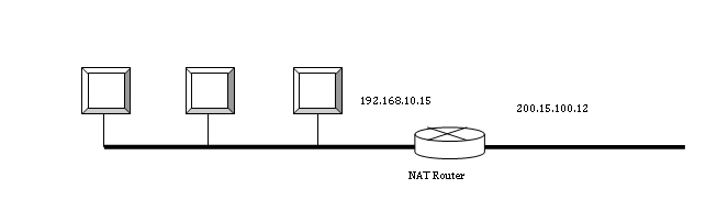
The rest of the Internet only sees the  global address which is
  but the private address is hidden.
Address translation
All packets intended for Internet goes through the router which change the source address with the global address. Similarly, incoming packet goes through the router in which destination address is changed to private addresses.
Translation table
The problem of sending packet with source address is solved by changing the source address at router. But routing to correct destination inside a private network from Internet is different problem.
This is done using a translation table.
Using one ipaddress
In this scheme, the translation table has two columns, private address and external address. When a packet is sent to external address, the router change the source address and also make a note of private address in the translation table of the source along with external address. When a response from the same destination is received, it is used as for identifying the private address of the destination in side .
In the scheme above, the communication is always initiated by private network. The is used by the  running many server programs, because the private network of organizations cannot run programs that need internet access.
For example, email server, etc.
Using a pool of ipaddress
In this scheme, the router uses four global addresses. So four private network hosts can communicate with the same external host because each address pair defines one connection.
\begin{aligned}
192.168.100.1 -> 200.15.100.20 -> 200.33.23.22\\ \\
192.168.100.2 -> 200.15.100.21 -> 200.33.23.22
\end{aligned}
There is few drawbacks with connections, first no more than  connection is allowed and second, a private network host cannot access two server programs at the same time.
Using both ipaddress and port number
To allow many-to-many connections, we need more information in the translation table.
If the translation table also has information for about transport layer then we have not problem creating more connections.
| Private Address | Private Port | External Address | External Ports | Transport protocol |
 |  |  |  | TCP |
 |  |  | | TCP |
| … | … | … | … | … |
When a response is received then a combination of source address and the destination port number decide the Host address of the destination private network.
The internal port number must be unique.
NAT and ISP
Suppose the has  addresses, but it has
 customers. To server
  customer it provide them with the private address and use to translate the addresses using one of the
  addresses.
References
Andrew S. Tanenbaum, David Wetherall. n.d. Computer Networks. Pearson, 23-Jul-2013.
Behrouz A. Forouzan, Sophia Chung Fegan. n.d. Data Communications and Networking, Fourth Edition. McGraw hill education.