Table of Contents
In this lesson, you will learn about -logic gates. The logic gates are building blocks of digital circuit to which voltage and current are applied to as binary logic 0 or 1. Voltage or current applied to analog circuits such as telephone systems as analog signals with continuous range from 0 to 5 V.
Binary Logic System
A digital circuit recognize only 1 and 0, so in this voltage operated circuit – a low voltage 0V is binary 0 and a high voltage 5V is binary 1.
In real world, these voltages are not absolute, but voltage has an acceptable range of values.
For example
\begin{aligned}
&3V \hspace{3px}to \hspace{3px}5V \hspace{3px}is \hspace{3px}1\\\\
&0V \hspace{3px}to \hspace{3px}0.2V \hspace{3px}is \hspace{3px}0
\end{aligned}
Positive Logic System
In this system, the low voltage to the circuit, 0V is considered as logic 1 and high voltage 5V is a 0 logic.
Negative Logic System
In this system, when the input voltage is 0V it is logic 0 and the high voltage to the input is considered as logic 1.
Basic Gates
The logic gates are the fundamental hardware devices to which input voltage is applied and it produces a specific logical response as output.
You can derive other gates from the basic logic gate types or create simple digital circuits. Understanding logic gates properly is very important in learning higher concepts in digital circuit design.
Types of Basic Gates and their Symbols
There are three types of logic gates which are listed below.
- AND Gate
- OR Gate
- Not Gate
We will discuss the derived gate types in the next section.
AND Gate
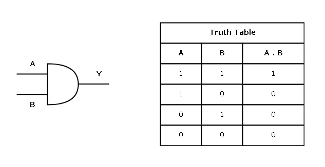
The AND gate work on the principle, “all or nothing”. An AND gate with two input A and B will send an output of 1, only when both A and B are 1, otherwise, the output will be false.
Output from an AND gate with all possible combination of inputs for A and B is usually written in a table called the Truth Table.
The expression  denotes an AND operation on A and B. The logic symbol and truth table for AND gate is given below.
OR Gate
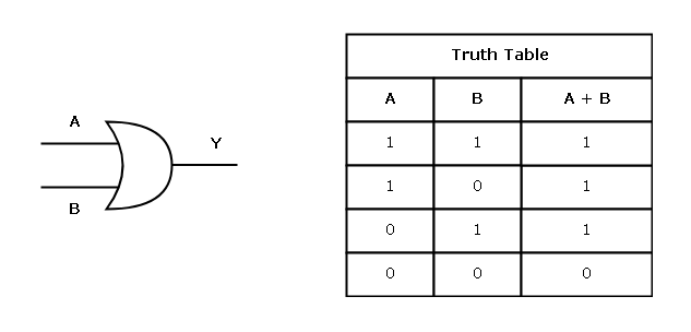
The logic of OR gate is different, and it says, “If any input of an OR gate is 1, then the output will be 1”. This gate does not need both input to 1 for an output to be 1.
The OR operation is denoted by a “plus” sign –  , which means A or B. The logic symbol and truth table for OR gate is given below.
NOT Gate
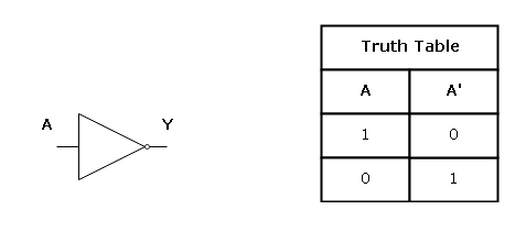
The NOT gate is used as an inverter in a digital circuit. If the input is 1, then the output becomes 0 and if the input is 0, then the output is 1.
The NOT operation is denoted as A’ if performed on a single input variable A. The logic symbol and truth table for the NOT gate is given below.
These are the basic gates and building blocks of all kinds of digital circuits. In the next lesson, we will discuss about derived gates like NOR, NAND, XOR, etc.
References
- John.F.Wakerly. 2008. Digital Design: Principles And Practices, 4/E. Pearson Education, India.
- Mano, M. Morris. 1984. Digital Design. Pearson.